
Introduction
A LiFePO4 battery reaches its target charging voltage.
But current is still flowing.
Should the charger stop immediately?
Should it wait until current falls to:
- 10A?
- 5A?
- 1A?
- Zero?
Or should the battery remain connected to the charger indefinitely?
This question becomes important when configuring:
- Bench chargers
- AC chargers
- Solar charge controllers
- Hybrid inverters
- Battery test equipment
Charging a lithium battery is not simply:
Reach one voltage number and switch off.
The system may use several conditions to determine that charging is complete.
These can include:
- Charging voltage
- Charging current
- Time
- SOC
- BMS communication
Understanding charge termination helps prevent two opposite problems:
Stopping too early and holding the battery at high voltage unnecessarily.
Review the CC/CV Charging Process
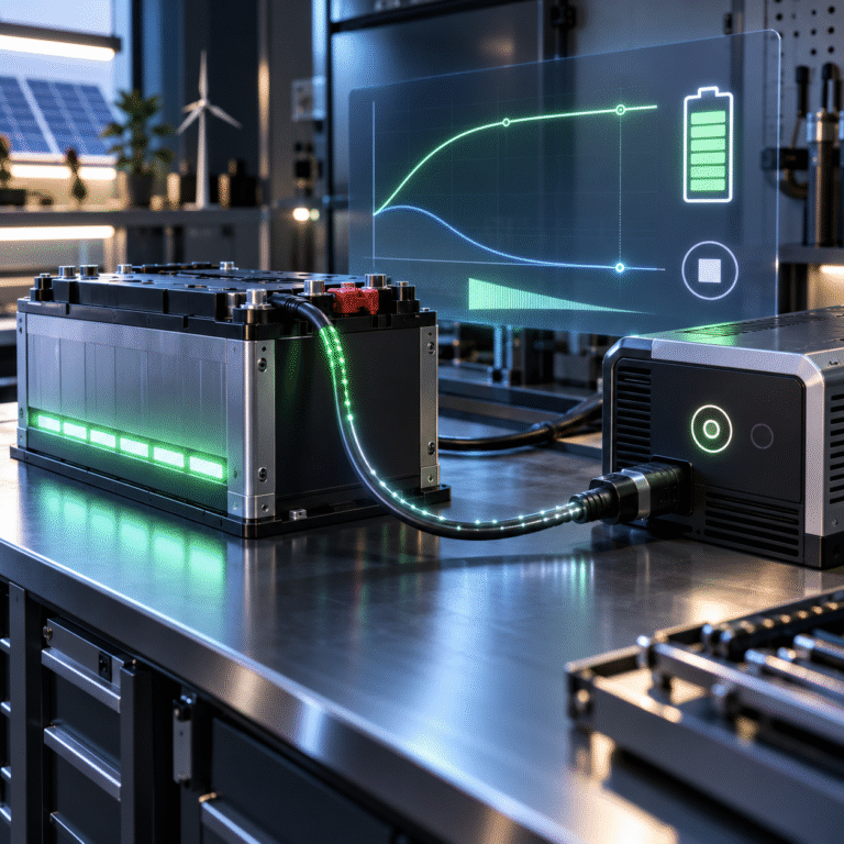
LiFePO4 charging is commonly described as: CC/CV
or: Constant Current / Constant Voltage
Constant-Current Stage
The charger supplies a controlled current.
Battery voltage gradually rises.
Constant-Voltage Stage
Battery reaches the charging-voltage target.
The charger holds approximately this voltage.
Charging current begins to decrease.
The decreasing current near the end is often called: tail current
Why Does Current Fall?
Once the battery reaches the charger’s voltage limit, the charger cannot continue forcing the same current without allowing voltage to rise further.
Therefore, current naturally decreases.
For example: 50A → 35A → 20A → 10A → 5A
This is normal near the end of a CC/CV charge.
Does Current Need to Reach Zero?
Normally, no.
Waiting indefinitely for current to reach exactly zero is usually unnecessary.
A battery system always contains small electrical effects such as:
- BMS consumption
- Balancing current
- Display consumption
- Communication modules
The charger may therefore continue showing a small amount of current.
Charge completion should follow the battery manufacturer’s termination criteria rather than an assumption that current must become exactly 0.00A.
What Is Tail Current?
Tail current is the reduced charging current observed near the end of the constant-voltage stage.
It can also be used as one condition for determining when charging is complete.
For example, a charging system might consider the battery full when:
- Target voltage has been reached
and
- Current has fallen below a defined threshold
for a certain time.
The exact threshold depends on:
- Cell design
- Battery capacity
- BMS
- Charger strategy
Why Express Tail Current as a Percentage of Capacity?
A fixed current means different things for different battery sizes.
Consider: 5A tail current
For a 50Ah battery: 5A = 0.1C
For a 500Ah battery: 5A = 0.01C
The same 5A represents a very different end-of-charge condition.
Therefore, engineers often think in terms of C-rate rather than one universal current.
Example: 100Ah Battery
Suppose a 100Ah battery is charged.
Near the end:
Charging current falls from: 20A → 10A → 5A → lower
If the battery manufacturer’s charge-termination logic uses a low C-rate threshold, the charger may stop after both voltage and current conditions are satisfied.
Do not invent a generic threshold without checking the product specification.
Why Stopping the Moment Voltage Is Reached Can Be Too Early
Imagine a battery reaches its charging-voltage target while current is still: 50A
If the charger switches off immediately, the battery may not have completed the desired charging process.
High current can temporarily push terminal voltage upward due to:
- Internal resistance
- Polarization
When charging stops, voltage may relax.
Therefore, many chargers allow some constant-voltage time before terminating.
But Holding High Voltage for Hours Is Also Unnecessary
Now consider the opposite approach.
The battery reaches its charging target.
Current falls to a very low level.
But the charger continues holding the battery at its upper charging voltage for: six more hours
This may provide very little additional stored energy.
For LiFePO4, prolonged high-voltage holding is generally unnecessary compared with traditional lead-acid absorption charging.
The objective should be:
complete the required charging process, then stop or move to the appropriate standby strategy.
This Is Where Lead-Acid Chargers Can Cause Confusion
Lead-acid chargers may hold absorption voltage for:
- One hour
- Two hours
- Longer
because lead-acid chemistry uses a different charging process.
Applying the same long absorption stage to LiFePO4 simply because the charger supports it may not be necessary.
When converting from lead-acid to LiFePO4, review:
- Absorption time
- Float behavior
- Equalization
not only charging voltage.
Charge Termination Can Be Voltage-Based
Simple chargers may use primarily: Voltage threshold
When battery voltage reaches the programmed target, the charger:
- Reduces current
- Stops
- Enters standby
This is easy to implement.
However, voltage alone does not always provide the most precise indication of SOC.
Charge Termination Can Be Current-Based
More advanced chargers may use: Voltage + tail current
For example: Target voltage reached.
Then current must fall below a defined threshold.
Only then is charging considered complete.
This prevents immediate cutoff caused only by a temporary voltage rise.
Charge Termination Can Be Time-Based
Some systems use:
- Maximum constant-voltage duration
- Absorption time
- Safety timer
Time provides another layer of control.
For example, if current never falls as expected because a load is operating, the charger may not remain indefinitely in the same stage.
Loads Can Confuse Tail-Current Detection
This is a very important ESS issue.
Suppose: Charger output = 20A
House load consumes the battery-side equivalent of: 15A
Only: 5A
actually enters the battery.
Depending on where current is measured, the charger may see 20A while the BMS sees only 5A.
If charge termination is based on charger-output current instead of true battery current, the system may remain in the charging stage longer.
Measurement location matters.
A Battery Can Be Full While the Charger Still Delivers Power
Imagine: Battery is full.
The charger supplies: 10A
But active DC loads consume: 10A
Net battery current is approximately zero.
The charger is supplying loads rather than continuing to store energy in the battery.
Therefore:
Charger output current is not always battery charging current.
This distinction is especially important in telecom and off-grid systems.
BMS SOC Can Also Be Used
In a communicating ESS, the inverter may receive: SOC = 100%
from the BMS.
The system may then reduce or stop charging.
However, SOC itself is an estimate.
It may be based on:
- Coulomb counting
- Voltage
- Current history
- Calibration
Therefore, many systems combine SOC with:
- Cell voltage
- Charge-current limit
- Pack voltage
rather than relying on SOC alone.
What Does the BMS Do Near Full Charge?
The BMS may:
- Reduce Charge Current Limit
- Reduce Charge Voltage Limit
- Balance cells
- Report 100% SOC
- Eventually request zero charging current
This allows a compatible inverter to terminate charging dynamically.
Cell Balancing Can Extend the Finishing Stage
Suppose most cells are nearly full.
One or two cells are slightly lower.
The BMS begins passive balancing near the upper voltage range.
The charger may remain at a low current while balancing takes place.
This can make the final few percent of charging take much longer.
Does the Battery Need to Stay at 100% Until Balancing Finishes?
Not necessarily every day.
The required balancing strategy depends on the BMS.
Some batteries may benefit from periodically reaching the upper balancing region.
That does not mean the battery must remain there for many hours during every charging cycle.
Follow the battery manufacturer’s recommendation.
Why “100% SOC” and “Charging Finished” Are Not Always Identical
A BMS can display: 100%
while a small charging current continues.
Possible reasons include:
- SOC display rounded to a whole percentage
- Cell balancing
- Charger finishing logic
- SOC calibration
Likewise, a battery can reach target voltage before the BMS displays 100%.
These values describe different aspects of the charging process.
Charge Termination for Solar Systems
Solar charging introduces additional complexity because available power changes continuously.
Near sunset:
- Solar current decreases
- Battery may be below full
- Current becomes very small
This is not charge termination.
It is simply insufficient solar power.
The system should distinguish:
Current is low because battery is full from Current is low because the sun is weak.
Example: Morning Full-Charge Finishing
Suppose:
Battery SOC = 95%
PV available = 5kW
Battery reaches charging-voltage target.
Current gradually falls.
This may be normal charge termination.
Now compare:
Battery SOC = 55%
PV available = 300W
Current is also low.
The cause is completely different.
How Can the System Tell the Difference?
Check:
- Battery voltage
- SOC
- Highest cell voltage
- BMS charge-current limit
- PV available power
- Active loads
No single value tells the whole story.
What About Standalone AC Chargers?
A standalone LiFePO4 charger may use an automatic algorithm such as:
- Constant current
- Constant voltage
- Current falls below termination threshold
- Charger stops or enters standby
This is generally preferable to a simple DC supply left connected indefinitely without proper control.
Can a Laboratory DC Power Supply Charge LiFePO4?
Technically, a regulated CC/CV power supply can charge a LiFePO4 battery when operated correctly.
However, it may lack:
- Automatic termination
- Reverse-current protection
- Lithium-specific protection
- Automatic restart logic
It is better suited to:
- Laboratory testing
- Commissioning
- Skilled technical use
rather than unsupervised consumer charging.
Why Charger Restart Logic Matters
After charging stops, battery voltage relaxes.
If the charger restart threshold is too close to the cutoff voltage, it may repeatedly:
charge → stop → restart → stop
This can create unnecessary micro-cycling.
A sensible restart condition should provide enough difference between:
- Charge completion
- Recharge initiation
according to the battery system design.
Example of Poor Restart Logic
Charge ends at high voltage.
Battery relaxes slightly.
Within five minutes, voltage falls below restart threshold.
Charger begins again.
The process repeats throughout the day.
The customer sees constant charging-state changes.
The problem may be the charger hysteresis—not the battery.
Does Float Charging Solve This?
Traditional lead-acid systems use float to maintain full charge continuously.
LiFePO4 does not require the same strategy.
Depending on system design, the charger may:
- Stop
- Enter standby
- Use a lower maintenance voltage
- Follow BMS commands
Do not assume traditional lead-acid float is required.
Charge Termination and Battery Lifetime
Charging strategy affects how much time the battery spends near its upper SOC region.
A battery that is:
- charged normally
- reaches its target
- then begins normal usage
is different from a battery held continuously at its highest charging voltage.
For daily cycling ESS applications, there is usually little reason to extend the finishing stage unnecessarily.
Commercial ESS Uses More Sophisticated Logic
A commercial energy-storage controller may consider:
- SOC target
- Energy price
- Battery temperature
- Cell voltage
- Charge current
- Scheduled dispatch
The system may intentionally stop charging at:
- 80%
- 90%
- 100%
depending on operational strategy.
“Full charge” is therefore not always the daily goal.
Troubleshooting a Charger That Never Stops
Check:
- Is a load consuming current?
- Is battery voltage reaching the target?
- Is tail current measured at charger or battery?
- Is absorption time too long?
- Is SOC calibration inaccurate?
- Is one cell preventing stable completion?
- Is the charger using lead-acid mode?
A charger remaining active does not automatically mean the battery is still storing significant energy.
Troubleshooting a Charger That Stops Too Early
Check:
- Charge-voltage target
- Cable voltage drop
- High cell voltage
- Cell imbalance
- Charger termination threshold
- BMS charge-current limit
- Battery temperature
Do not immediately raise charging voltage.
Identify the actual reason for early termination.
For Distributors: Useful Customer Data
Ask customers to provide:
- Battery capacity
- Starting SOC
- Target voltage
- Current when voltage target is reached
- Current when charger stops
- Highest cell voltage
- Lowest cell voltage
- BMS SOC
- Charger mode
This allows the end-of-charge behavior to be evaluated properly.
Conclusion
LiFePO4 charging does not need to continue until current reaches exactly zero.
A well-designed charger can determine charge completion using a combination of:
- Voltage
- Tail current
- Time
- SOC
- BMS instructions
The goal is to complete the required charge without either:
stopping prematurely or holding the battery unnecessarily at high voltage.
HIZN provides LiFePO4 energy storage batteries with model-specific charging-voltage, current and BMS parameters for solar, residential, telecom and commercial applications.
If you need to configure a charger for a HIZN battery, send us the battery model, charger model and application. We can provide the corresponding charging parameters and help review the charge-termination settings.