
Introduction
Industrial motors do not always consume electricity. Under certain operating conditions, they can temporarily act as generators.
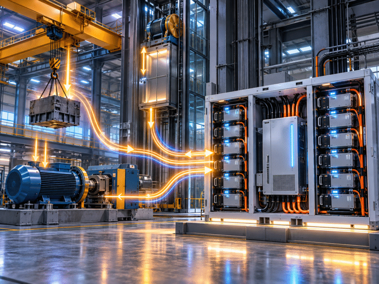
An elevator descending with a heavy load, a crane lowering material, a centrifuge decelerating or a large motor being rapidly slowed can return electrical energy to its drive system. Traditionally, some of this energy is dissipated as heat through braking resistors. This creates an attractive idea: instead of wasting the regenerative energy as heat, can it be stored in a LiFePO4 battery?
The answer can be yes, but the battery should not normally be connected directly to an industrial VFD DC bus without a properly engineered power-conversion and protection system. Regenerative energy can be fast, intermittent and high-power, while the battery BMS imposes clear limits on charging voltage, current, SOC and temperature.
A successful energy-recovery system therefore requires coordination between the motor drive, DC or AC bus, bidirectional converter, BMS and energy-management strategy.
Where Does Regenerative Energy Come From?
A motor consumes electrical energy when it produces torque in the direction needed to accelerate or drive a mechanical load. Under different mechanical conditions, the rotating equipment can force the motor to generate energy back toward the drive.
For example, when an elevator car descends under a heavy load, gravity can drive the motor. A crane lowering a container can behave similarly. During deceleration, rotating inertia can also return energy. The drive must do something with this electrical power. If it cannot send energy back to the grid or into storage, DC bus voltage rises.
Traditional Braking Resistors Turn Energy into Heat
Many VFD systems use a braking chopper and resistor. When DC bus voltage rises during regeneration, the chopper connects the resistor and dissipates the excess energy as heat. This approach is simple and reliable, but the recovered mechanical energy is lost.
In applications with frequent braking or lowering cycles, the wasted energy can become significant. An energy storage system offers another possibility: capture part of that power and reuse it later.
Do Not Connect a 51.2V Battery Directly to a 600V VFD Bus
Industrial AC drives often have DC-link voltages far above low-voltage battery systems. For example, equipment operating from a 400V-class three-phase AC supply can have a DC bus in the several-hundred-volt range.
A 51.2V battery cannot be directly connected to such a bus. Even a high-voltage battery rack should not be connected merely because the nominal voltages appear similar. A controlled bidirectional DC/DC converter or suitable PCS architecture is required to manage voltage, current, precharge and protection.
AC-Coupled Energy Recovery Is One Approach
One architecture uses a regenerative motor drive that can send energy back to the facility AC bus. A bidirectional ESS PCS connected to the same AC bus can then absorb available real power and charge the battery.
The energy path becomes: Motor → Regenerative Drive → AC Bus → PCS → LiFePO4 Battery
This has the advantage that the motor drive and battery ESS remain separate systems connected through a standard AC electrical bus. The EMS can decide when the battery should absorb the regenerated power.
DC-Coupled Energy Recovery Is Another Approach
Another architecture can connect storage to a common DC bus through a bidirectional DC/DC converter. The converter controls energy flow between the industrial DC link and battery. This can reduce conversion stages in some systems, but it requires much closer engineering coordination.
The converter must handle the VFD bus voltage, battery voltage range, regeneration power and dynamic response. It also needs to ensure that the battery never receives current beyond the BMS’s permitted charge limit.
Regenerative Power Can Arrive Very Quickly
Solar charging often changes over seconds or minutes. Industrial braking events can change much faster. A crane may transition from lifting to lowering within seconds. A machine spindle can regenerate strongly during rapid deceleration.
The storage converter must therefore respond quickly enough to prevent the drive DC bus from rising excessively. A battery may have plenty of unused kWh capacity but still be unable to absorb a sudden power pulse if its charge-current limit or PCS power rating is too low. This is why kW capability can be more important than kWh capacity in regenerative applications.
Example: A Short High-Power Braking Event
Suppose a machine generates: 100kW
for only: 10 seconds
Energy produced is approximately: 100kW × 10/3600h ≈ 0.28kWh
The energy quantity is small compared with a 50kWh battery. However, the instantaneous power is 100kW. A battery system with 50kWh of capacity but only a 30kW PCS cannot absorb the complete 100kW event directly. Some energy will need to be handled elsewhere, such as the grid or braking resistor.
kWh Alone Is Therefore Misleading
A buyer might think: “The regenerative energy per cycle is only 0.3kWh, so a 10kWh battery is more than enough.” From an energy perspective, that may be true.
But if the 0.3kWh arrives within several seconds, the power can be extremely high.
The ESS design must satisfy both: Energy requirement in kWh and Peak regenerative power in kW
The battery BMS, PCS and DC distribution all need to support the power requirement.
Battery SOC Determines Whether Regeneration Can Be Accepted
A battery at 40% SOC may have substantial room to absorb regenerative energy. A battery already near 100% SOC may have very little charging headroom. If the industrial machine regenerates regardless of battery SOC, the system needs another path for excess energy.
This could be:
- Grid export
- Braking resistor
- Mechanical control
- Curtailment
- Another energy-storage device
The battery must never be the only protection against an overvoltage event when it may already be full.
Keep the Braking Resistor as a Safety Layer Where Required
In many industrial designs, adding battery storage does not mean the braking resistor should automatically be removed.
The resistor can remain as a backup sink for regenerated power when:
- Battery is full
- BMS blocks charging
- PCS is unavailable
- Regenerative power exceeds PCS capacity
- Communication fails
This creates a more robust system. The energy-storage system captures useful energy under normal conditions while the resistor still protects the drive during abnormal conditions.
BMS Charge Current Limit Must Be Respected
Suppose the battery can currently accept only 150A. The converter cannot simply push regenerative power into the battery because the motor generated it.
The BMS may reduce charge current because of:
- High SOC
- High cell voltage
- Temperature
- Cell imbalance
- Module availability
A communicating PCS or DC/DC converter should respect the BMS Charge Current Limit. If the BMS limit falls, regenerative power must be redirected elsewhere.
High-Voltage Batteries Can Be Better Suited to Industrial Power Levels
A 100kW regenerative event on a 51.2V battery would theoretically require current approaching: 100,000W ÷ 51.2V ≈ 1,950A
before losses and operating-voltage differences. This is impractical for many low-voltage systems.
At 500V DC, the same 100kW requires around: 200A
This is one reason larger industrial ESS often uses high-voltage battery architecture. System voltage significantly affects the current required to absorb regenerative power.
Battery Power Capability Depends on More Than BMS Rating
A battery may have a 200A BMS, but that does not automatically mean it should absorb 200A regenerative pulses continuously. The cell charge-rate capability, busbars, thermal design and battery manufacturer’s recommended current all matter.
Regenerative systems should use approved continuous and peak charge ratings rather than assuming the BMS electronic limit defines the battery’s full power capability.
Repeated Regeneration Can Create Thermal Load
One short braking event may create little battery heating. A crane operating hundreds of cycles per shift is different. The battery and converter can repeatedly absorb high current with only short intervals between events.
Average thermal load can therefore become substantial even if each individual pulse is brief. The design should consider duty cycle, not only maximum power.
Elevators Are a Good Example
An elevator alternates between motoring and regenerative operation depending on direction, load and counterweight balance. In a busy commercial building, this can occur frequently. A building-level ESS may be able to absorb part of that regenerated power if the elevator drive is regenerative and the electrical architecture allows energy to return to the AC bus.
However, the economics depend on how much energy is actually recoverable, how often the events occur and whether the building already has loads consuming that power. Not every elevator installation produces enough exportable energy to justify dedicated storage.
Cranes Can Produce Larger Regenerative Pulses
Port cranes, mine hoists and industrial lifting systems can move heavy masses through substantial vertical distances. During lowering, significant energy can be regenerated.
These applications can be attractive for energy recovery, but peak power can be very high. A battery ESS may need a large PCS even if the total energy recovered during one cycle is modest. The system should be designed from actual load profiles and regenerative measurements rather than rough estimates.
Machine Tools Can Regenerate During Deceleration
Large spindle motors, test stands and centrifuges can regenerate when they slow down rapidly. The duration may be short, but repeated deceleration cycles can waste meaningful energy through braking resistors.
In some factories, a common DC bus connects several drives so energy generated by one machine can be consumed by another before storage is considered. Battery storage becomes most valuable when regenerative energy exceeds simultaneous plant demand.
The Facility Load Can Absorb Energy Before the Battery
In an AC-coupled system, regenerative energy enters the facility AC bus. If other equipment is consuming power at that moment, the regenerated power may simply reduce grid import.
For example, a motor returns 50kW while the factory consumes 200kW. Grid import temporarily falls from 200kW to approximately 150kW. There is no surplus energy requiring battery storage. The battery becomes useful when regeneration exceeds immediate local demand or when capturing the energy creates another operational benefit.
Grid Export Rules Can Influence the Design
If the facility is permitted to export regenerative energy to the utility grid, the PCS may not need to absorb every transient. If export is prohibited, the EMS needs to maintain zero export.
This can require the battery to absorb surplus power quickly or the industrial drive to divert it to a resistor. Zero-export industrial energy recovery is therefore partly an EMS control problem.
The Battery Needs SOC Headroom Before the Event
If regenerative capture is important, the EMS may deliberately keep the battery below a maximum SOC. For example, instead of charging to 100% every morning, the system may hold around 70–80% so that there is room to absorb crane or elevator energy later.
This is similar to leaving headroom for midday solar. The optimum SOC target depends on expected regeneration, backup requirements and normal battery dispatch.
Fast Dynamic Control Is Essential
A slowly updating cloud-based EMS is not enough for millisecond-scale protection. Fast power-control loops must exist locally in the drive, PCS or DC/DC converter.
Higher-level EMS software can set operating targets, but the equipment itself must handle rapid changes safely. The braking resistor or drive protection remains responsible for very fast events that exceed storage capability.
Communication Failure Must Not Cause DC Bus Overvoltage
Suppose the battery PCS loses CAN communication with the BMS during a crane lowering event. The industrial system cannot assume that the battery is still available to absorb power.
A safe design should fall back to another energy path or stop accepting regeneration into the storage channel. The VFD braking system must remain protected independently. Battery communication cannot be the only defense against an industrial overvoltage event.
Example: 60kW Regenerative Crane
Imagine a crane regenerates approximately 60kW during lowering for 20 seconds.
Energy per event is: 60 × 20/3600 ≈ 0.33kWh
If this happens 100 times per day, the theoretical regenerative energy becomes substantial. However, the storage system still needs enough power capability to absorb 60kW at each event.
A 100kWh battery with a 30kW PCS would be energy-rich but power-limited. A smaller battery with a 75kW PCS could potentially capture more of each event, assuming its battery charge-current capability is sufficient.
Supercapacitors Can Sometimes Complement Batteries
Very short, extremely high-power regenerative events may suit high-power storage technologies such as supercapacitors. A hybrid system can use supercapacitors for rapid power pulses and batteries for longer-duration energy storage.
Whether this is justified depends on duty cycle, economics and system complexity. LiFePO4 batteries are well suited to many high-cycle applications, but not every power pulse needs to be solved with battery capacity alone.
Efficiency Should Be Evaluated Across the Full Energy Path
The recovered energy may pass through: motor → drive → AC/DC bus → PCS/DC-DC → battery
and later: battery → PCS → plant load.
Every conversion stage has losses. Therefore, the economic value of regenerative storage depends on round-trip system efficiency, energy price and number of cycles. A technically possible project is not automatically financially attractive. Measure real energy flow before sizing the ESS.
What Data Is Needed Before Designing the System?
For an industrial regenerative ESS, collect:
- Maximum regenerative power
- Duration of each event
- Events per hour/day
- Facility load during regeneration
- Drive/DC bus voltage
- Whether the drive is regenerative or resistor-braked
- Grid export permission
- Required battery capacity
- Required PCS/DC-DC power
- Battery SOC strategy
These values allow the designer to separate energy requirements from power requirements.
Commissioning Requires Dynamic Testing
A standard slow charge/discharge test is not enough.
The ESS should be tested under representative regenerative events while monitoring:
- PCS power
- Battery current
- BMS CCL
- DC bus voltage
- Braking resistor operation
- SOC
- Temperature
The system should also be tested with the battery near its upper SOC limit to confirm where regenerative power goes when storage is unavailable. That failure-mode test is critical.
Do Not Remove Existing Braking Protection Before Validation
One of the biggest mistakes in an energy-recovery retrofit is removing braking resistors too early because the battery is expected to absorb all regeneration. During initial commissioning, keep the original protection system available wherever the drive manufacturer requires it.
Only modify braking architecture according to an engineered design approved for the application. Industrial machine safety must take priority over maximizing recovered energy.
Conclusion
LiFePO4 energy storage can capture regenerative energy from motors, cranes, elevators and industrial drives, but the battery should not be treated as a simple replacement for a braking resistor.
The complete system must manage instantaneous regenerative kW, battery SOC headroom, BMS charge-current limits, PCS/DC-DC power, drive DC-bus voltage and fallback braking protection.
For industrial projects, kW capability can be more important than battery kWh because large amounts of power can arrive in very short periods.
HIZN supplies LiFePO4 batteries for commercial and industrial energy storage applications, including low-voltage and larger battery configurations.
If your project aims to recover regenerative energy, send us the peak regenerative power, event duration, battery voltage requirement, PCS/DC bus information and daily duty cycle. We can help identify the battery-side power and capacity requirements that should be coordinated with the industrial drive supplier.