
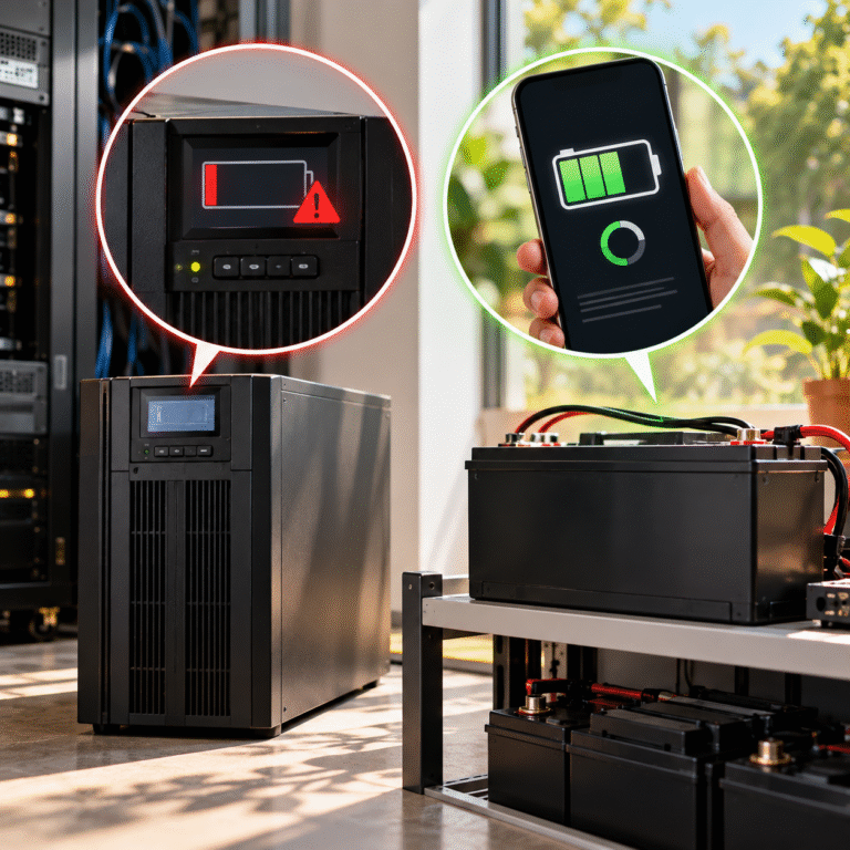
The UPS and BMS May Be Looking at Two Different Things
A LiFePO4 BMS can estimate SOC using coulomb counting. It measures current entering and leaving the battery and uses that data to estimate remaining capacity. A legacy UPS often has no access to this information. Instead, it monitors battery voltage and compares that voltage with internal limits originally designed around lead-acid batteries.
The result can be:
BMS SOC: 55%
while the UPS thinks: Battery almost empty.
Neither device necessarily has to be electrically defective. They are simply using different methods to make their decisions.
LiFePO4 Voltage Is Not a Simple SOC Gauge
LiFePO4 has a relatively flat discharge-voltage curve through much of its usable capacity. That is one of the chemistry’s useful characteristics because equipment receives relatively stable voltage during discharge. However, it also makes SOC estimation from voltage more difficult.
A battery can move through a substantial amount of energy while pack voltage changes only modestly. Near the lower SOC region, voltage can then begin falling more rapidly. A UPS designed around lead-acid behavior may therefore interpret the lithium voltage curve incorrectly.
Lead-Acid UPS Thresholds May Be Too Conservative
Suppose an older UPS expects a traditional 48V lead-acid bank. Its firmware contains a low-battery warning threshold and a final shutdown threshold designed to protect that type of battery. A 51.2V LiFePO4 battery has a different nominal voltage, discharge curve and BMS protection architecture.
If the UPS threshold is relatively high compared with the LiFePO4 battery’s intended operating range, the UPS may stop using the battery before its usable energy has been fully accessed. The customer then sees unused SOC remaining. This does not necessarily mean that the lithium battery has excessive reserve. It means the UPS and battery were not perfectly matched at the lower end of the voltage range.
Load Voltage Sag Can Trigger the Warning Early
Battery terminal voltage under load is not the same as resting voltage. Suppose the UPS is drawing 150A from the battery during an outage. Resistance exists in the cells, BMS, cables, breakers and terminals. The resulting voltage drop can push the UPS DC input below its warning threshold.
The UPS displays: Battery Low
The customer then removes the load or utility power returns. Battery current drops and battery voltage recovers immediately. The customer measures the battery and finds normal voltage.
This leads to the common complaint: “The battery voltage is fine, so why did the UPS say low battery?”
Because the important voltage was the voltage during the high-load event, not the voltage measured afterward.
A Simple Voltage-Drop Example
Assume the complete battery circuit has only: 10 milliohms of effective resistance.
At 50A:
Voltage drop is approximately: 50A × 0.01Ω = 0.5V
At 150A: 150A × 0.01Ω = 1.5V
The battery has not suddenly lost capacity. The higher current simply creates a larger voltage drop. If the UPS low-battery threshold is close to the loaded battery voltage, that additional 1V or 2V can significantly reduce usable runtime. This is why cable design becomes extremely important in low-voltage high-power UPS applications.
Cable Resistance Can Make the UPS See a Different Voltage
Suppose the battery terminals measure: 48.5V under load.
The UPS battery input terminals measure: 46.8V The difference of 1.7V is being lost between the battery and UPS.
Possible sources include:
- Undersized DC cables
- Long cable runs
- Loose lugs
- Circuit breakers
- Fuse holders
- Busbars
- Connectors
The BMS measures the battery internally and may still report healthy SOC. The UPS only knows that its input voltage is too low. Both readings can therefore be correct.
UPS Power Determines How Serious the Problem Becomes
A 51.2V battery supplying a 1kW UPS load does not experience the same current as one supplying 8kW.
Ignoring losses:
At 1kW: 1,000 ÷ 51.2 ≈ 20A
At 5kW: 5,000 ÷ 51.2 ≈ 98A
At 8kW: 8,000 ÷ 51.2 ≈ 156A
As UPS power increases, voltage drop becomes much more important. This explains why the same battery may appear perfectly normal under a light load but produce an early Battery Low warning when the UPS is heavily loaded.
BMS SOC Can Also Be Incorrect
It is equally important not to assume the BMS’s displayed 60% is always perfectly accurate. SOC is an estimate. A BMS commonly uses current integration together with voltage references and charging history. Small measurement errors can accumulate over time.
If a battery has operated for many weeks without reaching a valid SOC synchronization condition, the displayed SOC can drift. The battery may show 60% while actual remaining energy is substantially lower. Therefore, when UPS voltage and BMS SOC strongly disagree, both sides should be investigated.
Sudden SOC Correction Can Make the Problem More Obvious
A customer may observe: BMS SOC = 55%
then suddenly: BMS SOC = 15% shortly before shutdown.
This can happen when the BMS realizes from cell voltage that its previous coulomb-counting estimate was too optimistic. The battery did not physically lose 40% capacity in one second. The displayed estimate was corrected. This is particularly relevant after long periods of partial charging or unusual standby operation.
One Low Cell Can Trigger the End of Discharge
Pack SOC can look acceptable while one cell reaches its low-voltage limit earlier than the others. Because LiFePO4 cells are connected in series, the same current flows through every cell. If one cell has lower capacity, higher resistance or a different SOC, its voltage can fall faster under load.
The BMS eventually protects the whole pack. The remaining cells may still contain energy, but the battery cannot safely continue discharging because the weakest cell has reached its limit. This can produce a situation where displayed pack SOC still appears high shortly before shutdown.
Check Cell Voltage Under UPS Load
For this type of complaint, individual cell data is extremely useful.
Record:
- Highest cell voltage
- Lowest cell voltage
- Cell voltage difference
- Battery current
while the UPS is actually supporting the load. If all cells remain closely balanced but pack voltage is low mainly because of high current and external cable loss, the issue is probably system-level. If one cell collapses much faster than the others, battery-level investigation is necessary.
The UPS May Have More Than One Low-Voltage Threshold
Many UPS systems use several voltage levels. One threshold may trigger a warning. Another may begin controlled shutdown. A lower threshold may cause immediate DC shutdown.
The exact values can also depend on load or firmware. Therefore, seeing “Battery Low” does not necessarily mean the UPS will stop instantly. For lithium conversion, dealers should identify both the warning threshold and the final shutdown threshold where possible.
Runtime Protection Can Override Voltage
Some UPS systems also use estimated remaining runtime. For example, the UPS may begin shutdown when calculated runtime falls below a configured value even if DC voltage has not yet reached the final battery cutoff.
After a LiFePO4 retrofit, an inaccurate runtime model can therefore trigger earlier-than-expected warnings. This is another reason that battery compatibility includes more than nominal voltage.
A Lithium Battery Can Be Too Small in Power Even If kWh Looks Correct
Imagine a customer needs only 30 minutes of backup. Energy calculations show that one 5kWh lithium battery should theoretically be sufficient. However, the UPS load is 8kW.
The battery may have enough total energy for the required runtime but insufficient BMS discharge-current capability for 8kW. As current approaches the battery limit, voltage sag increases and the BMS may eventually protect. The system therefore shows Battery Low or shuts down earlier than expected. UPS battery selection must satisfy both:
kWh requirement and kW/current requirement.
Parallel Batteries Can Reduce Voltage Sag
When correctly designed, increasing the number of batteries in parallel can reduce current carried by each module. Suppose one battery would need to provide 150A. With three identical parallel modules, average current may be approximately 50A per battery if current sharing is good.
Lower module current generally reduces voltage sag and provides more discharge-current margin. This can improve both runtime and UPS low-voltage behavior. However, battery quantity should be selected according to approved parallel limits and proper DC bus design.
Parallel Current Sharing Must Be Verified
Three installed batteries do not guarantee perfect three-way sharing. If one branch has shorter cables or lower resistance, it may carry disproportionately high current. That battery reaches a lower voltage first and can disconnect.
The remaining modules then experience even more current. This can create a cascading shutdown. For UPS systems using parallel LiFePO4 batteries, branch current measurements under real UPS load can be very useful.
Temperature Can Increase Early Low-Voltage Warnings
Low temperature generally increases battery impedance and can reduce usable performance. A battery operating correctly in a 25°C test room may show more voltage sag in a cold equipment space. The UPS therefore reaches its low-voltage threshold sooner.
If customers complain mainly during winter or in cold warehouses, compare battery temperature with previous runtime tests. Temperature should be treated as part of the system condition.
UPS Calibration Can Matter
Some UPS equipment allows technicians to configure external battery quantity, battery capacity or runtime characteristics. If those settings still reflect the old VRLA battery configuration, low-battery predictions may not align with the new lithium bank.
Always review the UPS battery configuration after retrofit. Do not assume that physically replacing the battery automatically updates the UPS’s internal battery model.
What If the UPS Cutoff Cannot Be Changed?
Many legacy UPS systems have fixed firmware thresholds. If those thresholds significantly reduce usable LiFePO4 capacity, there may be no safe software setting that solves the problem.
In that situation, the installer has several possible choices depending on the application: accept the reduced usable SOC window, increase battery capacity, use a lithium battery specifically designed for that UPS voltage range or replace the UPS with equipment that supports lithium more appropriately. Do not modify internal UPS protection circuits simply to extract more battery energy.
Do Not Lower the Cutoff Until the BMS Becomes the Daily Shutdown Device
If the UPS allows manual low-voltage configuration, it can be tempting to keep lowering the threshold until maximum runtime is achieved. That is not necessarily good engineering. Normal UPS shutdown should generally occur with margin above the BMS’s emergency low-cell protection.
If every outage ends with the battery BMS opening its contactor, recovery behavior can become less predictable and the installation is relying on protection rather than normal control. The objective is coordinated shutdown, not maximum theoretical depth of discharge at any cost.
Dealer Troubleshooting Procedure
When an end customer reports “UPS says low battery but BMS still shows 60%,” collect these values at the moment of the warning:
| Parameter | Why It Matters |
|---|---|
| UPS DC input voltage | Determines what the UPS actually sees |
| Battery terminal voltage | Identifies cable voltage loss |
| BMS SOC | Compares battery estimate |
| UPS load in kW | Determines current demand |
| Battery current | Shows real discharge stress |
| Lowest cell voltage | Identifies weak-cell limitation |
| BMS alarm | Shows whether protection occurred |
| Battery temperature | Explains additional voltage sag |
| UPS low-voltage setting | Shows compatibility |
The most important rule is to capture data during the fault, not only after utility power returns.
For UPS Distributors: Test Low-SOC Behavior Before Selling the Combination
A battery may perform perfectly at 100% SOC and still behave poorly near the bottom of the discharge range. When validating a LiFePO4 battery with an UPS, test not only startup and charging but also controlled discharge toward the intended low-SOC operating point.
Observe when the UPS displays Battery Low, when the BMS reports low SOC and when final shutdown occurs. This provides much more useful compatibility information than a ten-minute test with a fully charged battery.
For Battery Dealers: Explain Usable Capacity, Not Only Nameplate Capacity
If a particular UPS stops at a relatively conservative DC voltage, customers may not be able to use the complete nominal battery energy. The distributor should include this in system sizing.
For example, if the customer needs 10kWh of usable backup energy, installing exactly 10kWh of nameplate battery capacity may be insufficient. The required oversizing depends on the real UPS cutoff and operating conditions. Professional sizing prevents future “unused SOC” complaints.
Conclusion
When a UPS says “Battery Low” while a LiFePO4 battery still displays 40%, 50% or 60% SOC, the battery is not automatically defective. The mismatch can result from lead-acid-based UPS voltage thresholds, high-load voltage sag, cable losses, inaccurate BMS SOC, cell imbalance, temperature or incorrect UPS battery configuration.
The key is to compare what the UPS actually sees at its DC terminals with what the battery BMS sees internally. For UPS and battery dealers, low-SOC discharge testing should be part of lithium compatibility validation—not only charging and full-SOC operation.
HIZN supplies LiFePO4 batteries for UPS, telecom and stationary backup applications with multiple capacity and BMS-current configurations.
If your customer sees an early Battery Low warning after a LiFePO4 retrofit, send us the UPS model, battery model/quantity, load power, BMS SOC, battery-terminal voltage and UPS DC-input voltage during the warning. We can help determine whether the limitation comes from UPS thresholds, installation losses or the battery itself.