
Introduction
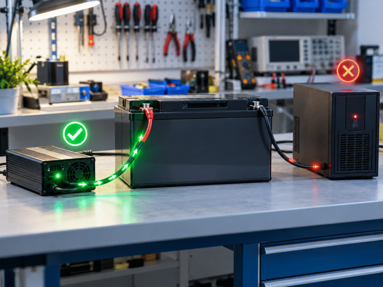
A customer reports that the LiFePO4 battery will not charge from the UPS. The battery remains at 40% or 50% SOC even though grid power has been available for hours. The UPS may show “Battery Full,” “Charging,” or no obvious error, but battery current remains close to zero.
The customer removes the battery and connects an external LiFePO4 charger. Immediately, charging begins normally. This appears to prove that the battery is healthy—and in many cases it does. But why can one charger charge the battery while the UPS charger cannot?
The answer usually lies in the difference between the UPS charger’s voltage/current strategy and the external charger’s lithium-specific output behavior. Two devices can both be called “48V battery chargers” while operating very differently. This is especially common when a legacy UPS designed for VRLA batteries is retrofitted with 51.2V LiFePO4.
Start with the Actual Charger Voltage
The first parameter to compare is voltage at the battery terminals. Do not rely only on a menu setting. Measure what the UPS charger actually produces while connected to the battery. If the UPS holds the DC bus at a voltage below the level needed for the LiFePO4 battery to accept meaningful charging current, very little energy will enter the battery.
An external lithium charger may operate at a higher approved voltage and immediately begin charging. The battery is therefore capable of charging; the UPS simply does not create enough voltage difference.
A “48V” UPS Charger Is Not One Standard Voltage
UPS systems described as 48V can use different numbers of lead-acid cells and different float/boost strategies. A UPS may be designed around a VRLA bank whose standby charging voltage happens to be lower than the LiFePO4 battery requires for normal recharge.
Another UPS may operate within an appropriate range. This is why nominal voltage labels are not sufficient. For retrofit approval, compare the complete UPS charger voltage range with the specific lithium battery charging specification.
The External Charger May Use CC/CV Charging
A dedicated LiFePO4 charger commonly uses controlled constant-current/constant-voltage behavior. When the battery is partially discharged, the charger raises its output enough to provide the configured current.
The UPS charger may instead be designed primarily to maintain a lead-acid float voltage with a relatively small recovery current. The two systems therefore interact with the lithium battery differently. The external charger can deliver 40A while the UPS supplies only 2A even though both are connected to the same battery.
Float Voltage Can Be Too Low for Significant Recharge
Suppose the battery’s present terminal voltage is close to the UPS float voltage. The voltage difference between charger and battery is small. Charging current therefore becomes low. The UPS may conclude that the battery is already close to full because its DC bus has reached the float target.
But the BMS SOC can still show only 60%. This is one of the clearest signs that lead-acid charger logic and lithium SOC are not well matched. The solution should be based on approved UPS and battery settings—not artificially raising voltage without limits.
Some UPS Systems Have a Higher Boost/Recharge Mode
A lead-acid UPS may normally maintain a lower float voltage but temporarily use a higher recharge voltage after a recognized discharge. If that boost stage is compatible with the LiFePO4 battery, recharge may work only after a real outage but not after another type of partial discharge.
This can create confusing behavior. For example, the customer discharges the lithium battery externally and reconnects it to the UPS. The UPS remains in float mode and supplies almost no current. After the UPS itself experiences a battery event, its charger enters recovery mode and suddenly charges faster. Understanding the UPS charging state becomes important.
The UPS May Think the Battery Is Already Full
A legacy UPS may use battery voltage to estimate whether charging is required. LiFePO4 has a different voltage curve from VRLA. A partially charged lithium battery can sit at a voltage that the UPS interprets as “nearly full.”
The UPS therefore provides only maintenance current even though the BMS reports substantial unused capacity. The external lithium charger does not rely on the same lead-acid assumption and continues charging according to its own voltage/current targets. This is a chemistry-integration problem rather than a failed battery.
The UPS Charge Current May Be Extremely Small
Some standby UPS systems have relatively modest chargers. The original battery bank may have been only a few small 7Ah or 9Ah lead-acid blocks. The charger might provide only a few amps.
If the UPS is upgraded to a 100Ah or 200Ah LiFePO4 battery, the charger technically charges it—but so slowly that the customer believes nothing is happening. For example, a 200Ah battery receiving only 2A would ideally require around: 100 hours to restore 200Ah from empty, before considering real charging behavior. A larger lithium battery can therefore expose how small the original UPS charger actually is.
Example: 200Ah Battery with a 5A UPS Charger
Suppose a 200Ah battery needs approximately 100Ah restored after an outage.
With a 5A charger: 100Ah ÷ 5A = 20 hours before accounting for changing current and losses.
With a 40A external charger: 100Ah ÷ 40A = 2.5 hours approximately.
The customer connects the external charger and sees dramatic progress, while the UPS appears almost useless. The UPS charger may not be defective at all. It is simply much smaller.
A Bigger Battery Does Not Automatically Upgrade the UPS Charger
This is a common lithium retrofit mistake. The customer replaces a small lead-acid battery bank with a much larger lithium battery to obtain longer runtime. Battery capacity increases by three or four times.
The UPS charger remains exactly the same. Backup runtime improves, but recharge time becomes extremely long. If outages are frequent, the battery may never fully recover before the next outage. The new system therefore needs to be designed for both backup duration and recovery time.
Charge-Current Settings May Be Limited in Software
Some larger UPS or hybrid systems allow technicians to configure maximum battery charging current. The setting may still be based on the original VRLA bank. For example, the charger hardware can provide 50A but the configuration limits it to 10A.
After lithium conversion, the dealer may decide that a higher current is appropriate—provided it remains within UPS, battery and AC-source specifications. Before assuming the charger is undersized, check its configured current limit.
BMS Charge Current Limit Can Also Reduce UPS Charging
In a closed-loop lithium system, the battery may communicate its allowable Charge Current Limit. If the BMS sends: CCL = 0A the UPS should stop charging. An external charger operating without CAN communication may not receive that command, although the battery’s internal BMS should still protect the cells.
If the external charger works while the UPS does not, check whether the UPS is receiving a zero or very low CCL from the BMS. This can occur because of temperature, high cell voltage, an alarm or communication interpretation.
Low Temperature Can Create Confusing Charger Differences
Imagine a battery in a cold environment. The BMS prohibits charging because cell temperature is below the approved range. A closed-loop UPS receives the BMS command and supplies zero current.
Later, the battery is moved indoors for testing. Temperature rises and an external charger works normally. The customer concludes that the UPS charger is defective. In reality, the two tests occurred under different battery temperatures. Always compare conditions at the same time.
A Charger Can Wake a Sleeping Battery
Some LiFePO4 batteries can be activated by applying an approved charging voltage. An external charger may provide that wake-up signal immediately. The UPS charger may not activate because its battery-detection circuit requires a minimum terminal voltage before enabling output.
This creates a circular problem: battery BMS is asleep → UPS does not detect battery → UPS charger stays off → battery cannot wake. An external charger breaks the cycle. This is one reason some deeply discharged batteries can be recovered externally even when the UPS cannot begin charging them.
Charger Detection Thresholds Matter
A battery charger does not always apply full voltage whenever AC power is present. For safety, some UPS chargers first check whether an appropriate battery is connected. If terminal voltage is below or above a defined range, the UPS may refuse charging.
The external charger may use a different detection range. Therefore, a deeply discharged lithium battery may be accepted by one charger and rejected by another. Review the UPS service documentation before assuming hardware failure.
A BMS Charge MOSFET or Contactor Can Behave Differently
Some batteries control the charging path separately. When an external charger is connected, its voltage may satisfy the conditions needed to close the charge MOSFET or contactor. The UPS float voltage may not.
The customer sees: external charger → charging current appears
UPS charger → zero current
This is another example where a small difference in charger output can produce very different BMS behavior. BMS logs and terminal voltage during the event help identify it.
Lead-Acid Equalization Is Not the Solution
If the UPS charge voltage is too low for the lithium battery, technicians may be tempted to enable a lead-acid equalization or high-voltage boost function. This is not an appropriate shortcut.
Equalization settings can exceed the battery’s approved charging voltage. The fact that a higher voltage makes current flow does not mean the setting is safe. Use only charging parameters approved for the specific LiFePO4 battery.
The External Charger Could Also Be Wrong
Do not assume that because the external charger makes current flow, it must be correct. An incompatible charger could force excessive voltage and trigger BMS protection later.
Before using the external result as evidence, confirm its output voltage and current are within the battery specification. A charger can appear to “work better” simply because it is too aggressive. The correct comparison is between two safe, approved charging profiles.
UPS Charger Voltage Should Be Measured Under Load
A charger might show an appropriate voltage with no battery attached but collapse once charging current begins. This can happen because of charger power limitation, AC input problems or internal faults. Therefore, measure voltage and current while the battery is actually connected.
If the UPS charger output drops significantly while the external charger remains stable, investigate the UPS power stage or input supply. Open-circuit voltage alone is not sufficient.
AC Input Limits Can Reduce Charger Power
Some UPS systems limit total AC input current. If the UPS is already supporting a heavy load, little input capacity may remain for battery charging.
For example, the UPS’s input-current limit may allow 20A total. Most of that current is already being used by the load. Only a small amount remains for battery recovery. An external charger connected to another AC circuit does not face the same limitation and therefore charges much faster. The battery is not the bottleneck.
Generator Mode Can Reduce Charging Current
UPS and inverter chargers often allow a lower charging current when operating from a generator. This protects the generator from overload.
If the system mistakenly remains in a generator or weak-grid mode while connected to utility power, recharge can be much slower than expected. Check the active operating mode. Again, compare actual battery current rather than relying only on the screen saying “Charging.”
Example: UPS Float Is Too Low
A customer installs a 51.2V LiFePO4 battery on a legacy UPS. The UPS maintains a DC voltage that is adequate for lead-acid standby operation but not high enough to complete the lithium battery’s approved charging process. The battery charges partially and then current falls almost to zero.
BMS SOC remains at 70–80%. A compatible external LiFePO4 charger raises the battery into its intended charging range and SOC increases normally. The battery is healthy; the UPS charging strategy is mismatched.
Example: UPS Charger Is Simply Too Small
Another customer has a 200Ah battery. The UPS charger provides 4A. The customer watches for an hour and sees SOC barely change. An external 40A charger makes the percentage increase quickly.
There is no fault. The two chargers differ by roughly a factor of ten in current capability. The correct business decision is whether the customer’s required recovery time justifies a larger UPS charger or an approved auxiliary charging solution.
Example: BMS CCL Is Zero
A modern UPS communicates with the battery over CAN. The battery temperature sensor reports a condition that makes the BMS set Charge Current Limit to 0A. The UPS follows the command and stops charging.
Later, during workshop testing, the external charger is connected under normal temperature and charging works. Comparing only the two chargers misses the actual cause. The BMS log reveals it immediately.
Can an External Charger Be Used Permanently?
Sometimes customers want to leave an external charger connected because the UPS charger is too slow. This can be possible in certain engineered systems, but it should not be improvised. Multiple chargers connected to one battery need coordinated voltage settings, total current limits, protection and AC/DC isolation.
The battery must never receive more combined charge current than allowed. For UPS installations, any auxiliary charger should be approved for the battery and coordinated with the UPS manufacturer where necessary.
Does the UPS Need to Know About External Charging?
If an external charger increases battery SOC independently, a legacy UPS may not accurately track that change. Its runtime or battery-percentage display can become even less reliable.
A BMS-connected system may handle the situation better, depending on architecture. This is another reason that adding an auxiliary charger is not purely an electrical decision. Monitoring and control should be considered as well.
Dealer Diagnostic Table
| Observation | Likely Direction |
|---|---|
| External charger high current, UPS almost zero | UPS voltage/current strategy |
| UPS charge voltage close to battery voltage | Insufficient voltage headroom |
| UPS charger only a few amps | Slow recovery by design |
| BMS CCL = 0A | Battery protection/control |
| External charger wakes battery | BMS sleep/low-voltage recovery |
| UPS refuses very low battery voltage | Battery detection threshold |
| UPS charger voltage collapses under load | UPS charger/input problem |
| Load consumes most AC input capacity | Power-budget limitation |
This narrows the issue before replacing either the battery or UPS.
For UPS Distributors: Compare Recharge Time Before Selling a Lithium Upgrade
Lithium batteries often provide more usable capacity than the VRLA bank they replace. That benefit can be wasted if the original UPS charger takes one or two days to restore the battery after an outage.
Before quoting a retrofit, calculate: energy used during outage ÷ practical battery charging power
This provides a realistic recovery-time estimate. For sites with frequent outages, charging power can be just as important as backup capacity.
For Battery Dealers: Ask for the UPS Charger Specification
When a customer says: “I have a 48V UPS. Can I use your 51.2V 200Ah battery?” do not check only the UPS discharge voltage.
Ask for:
- UPS charger voltage
- Float/boost behavior
- Charger current
- Battery detection range
- Low-voltage cutoff
- Actual UPS load
This makes the recommendation much more reliable. It also reduces the likelihood that a perfectly good large lithium battery later receives only a few amps of charge.
Conclusion
If a LiFePO4 battery charges normally from an external charger but not from the UPS charger, the battery is not automatically defective.
Common causes include UPS charge voltage that is too low, a very small built-in charger, lead-acid charging logic, BMS Charge Current Limit, battery-detection thresholds, low-temperature protection or limited AC input power.
The best diagnosis compares battery-terminal voltage and actual charging current from both charging sources under similar conditions.
HIZN supplies LiFePO4 batteries for UPS, telecom and stationary energy-storage applications and can provide model-specific charge-voltage and current requirements for integration.
If your customer’s battery charges with an external charger but not from the UPS, send us the UPS model, its charge voltage/current, battery model, BMS SOC and BMS CCL. We can help determine whether the issue is charger compatibility, charger power or battery protection.