
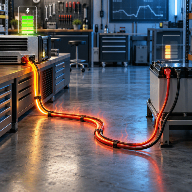
Introduction
The inverter shows: 56.8V
The charger is operating normally.
But a multimeter directly across the battery terminals shows: 55.9V
Which reading is correct?
Possibly both.
When charging current flows through cables, breakers, fuses, terminals and busbars, electrical resistance creates voltage drop.
The charger measures voltage at one location.
The battery experiences voltage at another.
If the difference becomes too large, the charging system may behave as if the battery has already reached its charging-voltage target—even though the actual battery voltage is lower.
Possible symptoms include:
- Charging current reducing too early
- Battery failing to reach expected SOC
- Long charging time
- Charger entering float prematurely
- Unequal charging between parallel batteries
- Hot cables or terminals
This issue becomes increasingly important as charging current increases.
Every Cable Has Resistance
Copper cable has low resistance, but not zero resistance.
Resistance depends on:
- Conductor material
- Cable cross-section
- Cable length
- Temperature
- Connections
When current passes through resistance, voltage is lost according to:
Voltage Drop = Current × Resistance
This means the same cable produces a larger voltage drop when charging current increases.
Why High-Current LiFePO4 Systems Are Sensitive
Consider a 51.2V battery being charged at: 100A
Even a resistance of: 0.01Ω
in the complete charging path produces: 0.01Ω × 100A = 1V
of voltage drop.
One volt may appear small.
But in a lithium charging system, a 1V difference between charger and battery terminals can significantly affect when the charger begins reducing current.
Where Does the Resistance Come From?
The total charging path can include:
- Positive battery cable
- Negative battery cable
- DC breaker
- Fuse
- Fuse holder
- Busbar
- Cable lugs
- Battery terminals
- Disconnect switch
- Contactor
Each component adds a small amount of resistance.
One component may be acceptable alone.
Together, their resistance can become significant.
The Charger Usually Measures Voltage at Its Own Terminals
Consider this simplified system:
Charger → 5-meter cable → battery
The charger is set to: 56.8V
At high current, the cable produces: 0.7V
of total voltage drop.
The charger sees: 56.8V
but the battery may see approximately: 56.1V
The charger believes it has reached its voltage target.
It may begin reducing current.
But the battery itself has not yet reached the same voltage.
The result can be premature charge taper.
Why the Problem Can Disappear at Low Current
Voltage drop is proportional to current.
Suppose the cable path produces: 0.007Ω
At 100A: Voltage drop = 0.7V
At 20A: Voltage drop = 0.14V
This explains an interesting observation.
During high-current charging, the charger and battery voltage may differ significantly.
When charging current falls, the readings become much closer.
This behavior strongly suggests resistance in the charging path.
Measure Voltage at Both Ends at the Same Time
When troubleshooting, measure:
Charger Output Terminals
Record DC voltage directly at the charger or inverter.
Battery Terminals
Record voltage directly at the battery.
Measurements should be made:
- At the same time
- While significant charging current is flowing
Measuring after charging stops is much less useful.
Once current falls to zero, cable voltage drop also approaches zero.
Both ends may then show almost identical voltage.
This Is Why Resting Measurements Can Miss the Problem
A customer switches everything off.
They measure:
Charger side: 52.8V
Battery side: 52.8V
They conclude:
“The cables are fine.”
But cable drop only becomes obvious under load or charging current.
The correct test is a loaded voltage-drop test.
Example: 51.2V 200Ah Battery
Suppose:
Battery: 51.2V 200Ah
Charging current: 80A
Charger voltage: 56.8V
Battery-terminal voltage: 56.2V
Difference: 0.6V
Estimated loop resistance: 0.6V ÷ 80A = 0.0075Ω
That resistance may come from:
- Cable length
- Cable size
- Connections
- Protection devices
The next step is to identify where most of the drop occurs.
Measure Individual Sections
Instead of only measuring the entire system, measure across individual components while current is flowing.
For example:
Positive Cable
Measure from charger positive to battery positive.
Negative Cable
Measure from charger negative to battery negative.
DC Breaker
Measure voltage directly across the breaker.
Fuse
Measure voltage across the fuse assembly.
Connector
Measure across suspicious terminals.
A component with unusually high voltage drop may have:
- Poor contact
- Loose connection
- Damage
- Corrosion
A Loose Terminal Can Create More Loss Than a Long Cable
Installers often focus only on cable cross-section.
But one loose cable lug can create substantial resistance.
Possible symptoms include:
- Localized heating
- Discolored terminal
- Melted plastic
- Charging-voltage instability
- Intermittent alarms
During commissioning, check both: electrical voltage drop and connection temperature
Heat and Voltage Drop Are Connected
Electrical power lost in a resistance becomes heat.
A simplified relationship is: Power Loss = Current² × Resistance
Suppose a poor connection has: 0.005Ω resistance
At 100A: 100² × 0.005 = 50W
Fifty watts concentrated in one terminal connection can generate significant heat.
This is why small resistance matters in high-current battery systems.
Long Cable Runs Need Larger Conductors
Imagine the battery cabinet is far from the inverter.
Longer cable means more resistance.
Possible solutions include:
- Larger cable cross-section
- Shorter cable run
- Higher system voltage
- Relocating equipment
Simply increasing charger power while keeping long undersized cables can make the problem worse.
Why 51.2V Systems Are Better Than 12.8V for High Power
For the same charging power, higher battery voltage means lower current.
Example:
Approximately 5kW at 12.8V requires several hundred amps.
Approximately 5kW at 51.2V requires around one quarter of that current before detailed voltage and efficiency calculations.
Lower current reduces:
- Cable loss
- Voltage drop
- Connector heating
This is one reason larger stationary energy storage systems commonly use 48V/51.2V or higher-voltage battery architectures.
Cable Size Cannot Be Selected from Current Alone
Cable selection should consider:
- Continuous current
- Cable length
- Allowable voltage drop
- Ambient temperature
- Installation method
- Cable insulation
- Local electrical regulations
- Terminal rating
A cable that can safely carry 100A without overheating may still produce too much voltage drop if it is very long.
Ampacity and voltage-drop requirements are related but different.
Parallel Batteries Create Another Voltage-Drop Problem
Consider four batteries connected in parallel.
If Battery 1 has:
- Short cables
while Battery 4 has:
- Much longer cables
their charging paths have different resistance.
Battery 1 may accept more charging current.
Battery 4 may accept less.
Over time, the batteries can show different SOC behavior.
Balanced cable design helps improve current sharing.
The Nearest Battery Should Not Do All the Work
A poor parallel arrangement may connect the inverter directly to the first battery.
Additional batteries are then daisy-chained behind it.
This can create uneven resistance.
The nearest battery may experience:
- Higher charging current
- Higher discharge current
- More cycling
- More heating
A properly designed common busbar can improve current distribution.
Busbars Must Also Be Sized Correctly
Installing large cables but using an undersized busbar simply moves the bottleneck.
Check:
- Busbar material
- Cross-section
- Current rating
- Bolt size
- Contact area
High-current ESS design should treat the complete DC path as one system.
What Is Remote Voltage Sensing?
Some professional chargers and controllers include:
remote voltage sense
Small sensing wires connect directly to the battery terminals.
The charger then measures actual battery voltage rather than only voltage at its own output terminals.
If charging cables lose 0.4V, the charger can compensate within its designed limits.
This can improve charging accuracy.
Remote Sensing Does Not Fix Bad Wiring
Voltage compensation is useful for normal cable loss.
It is not a solution for:
- Loose terminals
- Damaged connectors
- Undersized cables
- Excessively long cable runs
If the charger compensates by increasing output voltage across a poor connection, that connection can become even hotter.
Correct the wiring first.
Why a Charger May Enter Float Too Early
Suppose the charger switches from bulk/absorption to float when it senses: 56.8V
Because of cable drop: Battery itself = 56.0V
The charger reaches 56.8V at its own terminals and assumes the battery has reached the charging target.
It reduces current or enters float.
The customer sees:
- Battery not reaching expected SOC
- Charge current dropping early
This can resemble a battery-capacity problem.
Why Increasing Charger Voltage Is Not the Best First Solution
If the battery receives insufficient voltage because of cable loss, a user may increase the inverter setting.
For example:
56.8V → 57.6V
This may appear to work.
But if charging current later decreases, cable drop also decreases.
The battery could then receive a much higher voltage than intended.
The correct solution is to identify and reduce excessive voltage drop.
BMS Communication Does Not Eliminate Cable Drop
A battery may communicate perfectly with the inverter through CAN.
The BMS can report:
- Battery voltage
- SOC
- Charge-current limit
But the physical power cable still has resistance.
Communication cannot eliminate electrical loss.
Some sophisticated systems can compensate using BMS voltage data, but this depends on the equipment.
Good cable design remains essential.
Charger Voltage vs BMS Voltage
Small differences between readings are normal because of:
- Measurement accuracy
- Calibration
- Sampling time
For example:
Charger: 54.8V
BMS: 54.7V
may not be meaningful.
But a persistent difference of:
- 0.5V
- 1V
- More
under substantial charging current deserves investigation.
Why the Difference Changes with Charging Current
A very useful diagnostic pattern is:
At 100A
Voltage difference = 0.8V
At 50A
Difference = 0.4V
At 10A
Difference = 0.08V
This strongly suggests normal resistive voltage drop.
If the difference stays constant regardless of current, measurement calibration may also be involved.
Check Breakers and Fuse Holders
A common hidden source of voltage drop is not the cable itself but:
- Low-quality DC breaker
- Poor fuse holder
- Improperly tightened connection
High-resistance protection devices can become very hot.
Use equipment correctly rated for:
- DC voltage
- Current
- Interrupting capacity
AC breakers should not automatically be substituted for DC battery protection.
Temperature Can Make Resistance Worse
Copper resistance increases with temperature.
A warm cable therefore has slightly higher resistance than a cool cable.
More resistance creates more heating.
This can create a reinforcing effect in poorly designed high-current connections.
Adequate cable size and ventilation are important.
Example: Long-Distance Battery Installation
Suppose:
Inverter to battery distance: 8 meters
Because current must travel to the battery and back, the electrical loop length is substantially longer than the one-way distance.
At 100A, an undersized cable can create substantial:
- Voltage loss
- Heat
- Charging error
For this type of installation, increasing cable size or moving the inverter closer to the battery may be more practical.
Commercial ESS: Small Percentage Losses Become Large
Imagine a commercial battery charging at:
50kW
A 1% loss means:
500W
of continuous heat during charging.
At larger powers, DC distribution efficiency becomes a major engineering consideration.
This is one reason commercial ESS systems use:
- Engineered busbars
- Short DC connections
- High-voltage battery systems
- Thermal monitoring
Troubleshooting Checklist
When charger voltage and battery voltage do not match:
- Record charging current.
- Measure charger-terminal voltage.
- Measure battery-terminal voltage.
- Calculate the difference.
- Measure positive-cable voltage drop.
- Measure negative-cable voltage drop.
- Check breaker and fuse voltage drop.
- Inspect terminal temperature.
- Verify cable length and cross-section.
- Check meter accuracy.
Do this while the battery is actively charging.
For Distributors Handling Remote Troubleshooting
Ask customers to provide:
- Inverter/charger model
- Battery model
- Charging current
- Charger-side voltage
- Battery-terminal voltage
- Cable cross-section
- One-way cable length
- Breaker/fuse information
- Photos of cable connections
This often reveals whether the issue is battery-related or installation-related.
Common Mistakes
Avoid:
- Checking voltage only when charging is stopped
- Increasing charge voltage before checking cable loss
- Using long undersized battery cables
- Ignoring negative-cable voltage drop
- Assuming breakers have zero resistance
- Stacking many lugs on one battery terminal
- Using different cable lengths for parallel batteries
- Relying only on inverter-display voltage
Conclusion
The voltage displayed by a LiFePO4 charger is not always the exact voltage reaching the battery.
At high charging current, resistance in:
- Cables
- Breakers
- Fuses
- Busbars
- Connections
can create meaningful voltage drop.
This may cause the charger to reduce current prematurely even though the battery has not yet reached its intended charging voltage.
A professional charging system should therefore be designed for both:
current capacity and acceptable voltage drop
HIZN supplies LiFePO4 energy storage batteries for residential solar, commercial ESS, telecom and off-grid systems.
If a battery is charging slowly or charger voltage differs noticeably from BMS voltage, send us the battery model, charging current, cable size, cable length and inverter model. We can help identify whether excessive DC voltage drop may be affecting charging performance.