
Introduction
Connecting LiFePO4 batteries in parallel appears simple: connect all positive terminals together and all negative terminals together.
Electrically, this increases the available amp-hour capacity while keeping the nominal system voltage unchanged. However, a parallel battery bank can still perform poorly when the physical wiring creates unequal resistance between the batteries and the inverter.
The battery closest to the inverter may carry more current, heat up faster and reach its BMS protection limit earlier than the other batteries. Meanwhile, batteries farther from the main connection point may contribute less current and remain at a different state of charge.
For installers, distributors and energy storage system integrators, the objective is not only to create a parallel connection. The real objective is to create an electrically balanced parallel battery bank.
Why Parallel Batteries Do Not Always Share Current Equally
Current follows the path with the lowest total resistance.
In a battery bank, resistance comes from more than the battery cells. It also includes:
- Battery cable length
- Cable cross-sectional area
- Cable lug quality
- Terminal contact resistance
- Fuse and breaker resistance
- Busbar resistance
- Connection torque
- Corrosion or contamination at terminals
Even a small resistance difference can affect current distribution in a low-voltage, high-current energy storage system.
For example, imagine four 51.2V 100Ah batteries connected in parallel. The completed bank has:
- Nominal voltage: 51.2V
- Total capacity: 400Ah
- Nominal energy: 20.48kWh
If the inverter draws 160A, an ideally balanced system would supply approximately 40A from each battery. In practice, the current will not be perfectly identical, but one battery should not continuously carry a much larger share than the others.
Official battery wiring guidance recommends creating an equal current path through each parallel battery. This can be achieved with correctly arranged system connections or with positive and negative busbars using matched branch cables.
Three Common Parallel Wiring Layouts
1. Same-End or Daisy-Chain Connection
In this arrangement, the inverter positive and negative cables are connected to the same battery at one end of the bank.
This is easy to install, but it is usually the least balanced option for multiple batteries. The first battery has the shortest electrical path, while the last battery has the longest path through cables, terminals and interconnections.
The result may include:
- Unequal discharge currents
- Different battery temperatures
- Premature BMS disconnection
- Inconsistent SOC readings
- Reduced usable capacity from the complete bank
This arrangement should generally be avoided for larger parallel energy storage banks.
2. Diagonal Connection
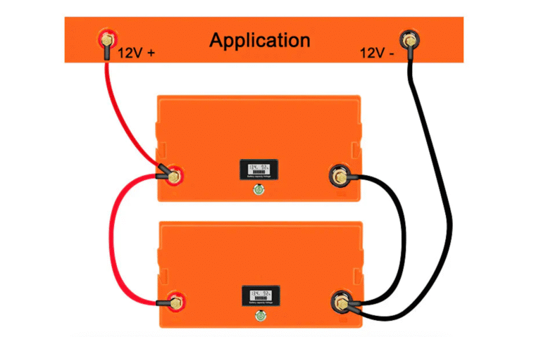
With a diagonal connection, the main positive cable is connected at one end of the battery bank, while the main negative cable is connected at the opposite end.
This creates a more similar total current path through each battery and is often suitable for a small number of parallel units.
For example:
- Main positive connection: Battery 1
- Main negative connection: Battery 4
A diagonal connection can improve current sharing without adding separate distribution busbars. Some battery manufacturers specifically recommend diagonal system connections when multiple batteries are installed in parallel.
However, as the number of batteries increases, the resistance of inter-battery links and terminals becomes more difficult to control.
3. Central Busbar Connection
For rack-mounted batteries, commercial ESS projects and larger battery banks, a positive and negative DC busbar arrangement is usually the preferred solution.
Each battery is connected individually to the common busbars.
For best results, every battery branch should use:
- The same cable material
- The same cable cross-sectional area
- The same positive cable length
- The same negative cable length
- The same lug type
- The same fuse or breaker model
- The same connection method
- The manufacturer’s specified terminal torque
This layout provides a clearer and more serviceable installation. It also makes individual battery isolation, current measurement and future expansion easier.
Step-by-Step Balanced Parallel Installation
Step 1: Confirm That the Batteries Can Be Paralleled
Do not assume that every LiFePO4 battery supports unlimited parallel expansion.
Check:
- Maximum supported parallel quantity
- Battery model and nominal voltage
- Capacity and BMS current rating
- Firmware version
- CAN or RS485 communication protocol
- Master-slave communication requirements
- DIP switch or address settings
Use batteries of the same model, voltage, capacity and preferably the same production generation. Mixing different battery types, ages or BMS designs can create unpredictable current distribution and protection behaviour.
Step 2: Match Battery Voltage and State of Charge
Before closing the parallel breakers, measure the open-circuit voltage of every battery.
Do not directly parallel batteries with a large voltage or SOC difference. The higher-voltage battery may rapidly charge the lower-voltage battery, creating a high equalisation current that does not pass through the inverter’s normal current-control system.
The acceptable voltage difference should follow the battery manufacturer’s instructions.
When adding batteries to an existing system:
- Isolate the operating battery bank.
- Charge or discharge the new battery to a similar SOC.
- Allow the batteries to rest.
- Measure the voltage again.
- Connect only after the values are within the approved range.
Step 3: Install Individual Branch Protection
Every parallel battery should have an independent DC-rated fuse or breaker on its positive branch.
Branch protection helps isolate a battery when there is:
- A cable short circuit
- An internal battery fault
- Incorrect polarity
- A failed connector
- Excessive branch current
The protection device must be selected according to the battery’s maximum current, cable ampacity, DC system voltage and prospective short-circuit current.
The BMS should not be treated as a replacement for external cable and branch protection.
Step 4: Use Equal-Resistance Battery Cables
Equal cable length is important, but equal resistance is the true objective.
For each branch, maintain consistency in:
- Conductor material
- Conductor size
- Cable length
- Number of bends
- Lug material
- Crimping method
- Fuse type
- Connection torque
Do not use a short cable for one battery and coil additional cable randomly on another. Route cables neatly and keep them protected from sharp edges, vibration and heat sources.
Step 5: Size the Main Busbar and Main Cable Correctly
The main DC conductors must be sized for the expected combined current of the complete battery bank.
A common installation error is to use suitable branch cables but an undersized main cable between the busbar and inverter.
The design should consider:
- Maximum continuous inverter current
- Peak or surge current
- Maximum charging current
- Cable installation method
- Ambient temperature
- Acceptable voltage drop
- Local electrical requirements
- Fuse and breaker ratings
The positive and negative busbars must also have sufficient current and short-circuit ratings.
Step 6: Configure Battery Communication
In a multi-battery system, power wiring and communication wiring are separate installation tasks.
Depending on the system design, installers may need to:
- Select one battery as the master
- Assign unique slave addresses
- Set DIP switches
- Install communication termination
- Connect CAN or RS485 cables in the correct order
- Select the compatible inverter protocol
A correctly wired DC system may still show incorrect SOC, charging limits or alarms when communication addresses are duplicated or the wrong protocol is selected.
Step 7: Connect the Inverter Through the Correct Start-Up Procedure
Many inverters contain large DC capacitors. Directly closing the main battery breaker may create a high inrush current.
Use the inverter’s approved pre-charge function, battery start button, pre-charge resistor or controlled start-up procedure when required.
Never repeatedly force a breaker closed when it trips during start-up. Check polarity, system voltage, pre-charge operation and inverter condition first.
How to Verify Equal Current Sharing
After installation, current sharing should be tested rather than assumed.
A practical field test includes:
- Fully inspect and energise the system.
- Apply a stable, moderate load.
- Measure every battery branch using a DC clamp meter.
- Record voltage, current, SOC and battery temperature.
- Increase the load gradually.
- Repeat the measurements.
- Check for loose or warm connections.
Small current differences are normal. A persistent large deviation may indicate:
- Unequal cable resistance
- Loose terminal hardware
- Different SOC levels
- Different battery internal resistance
- A restrictive fuse or breaker
- BMS current limiting
- Communication configuration errors
- A weak or ageing battery
The same test should also be performed during charging.
Example: Four 51.2V Rack Batteries in Parallel
For four identical 51.2V 100Ah rack-mounted batteries, a professional arrangement may include:
- Four equal-length positive branch cables
- Four equal-length negative branch cables
- One DC fuse or breaker for each battery
- One positive busbar
- One negative busbar
- One main battery breaker
- One correctly sized main cable set
- One master battery and three addressed slave batteries
- CAN or RS485 communication to the inverter
This configuration provides 20.48kWh of nominal energy while keeping the system at 51.2V.
Before installation, confirm that the selected inverter and battery model support the planned number of parallel units.
Frequently Asked Questions
Can batteries with different capacities be connected in parallel?
This is generally not recommended unless the manufacturer has specifically approved the combination. Different capacities and BMS limits can result in uneven current sharing and different charge or discharge cut-off times.
Must positive and negative battery cables be exactly the same length?
The positive cables should be matched with each other, and the negative cables should be matched with each other. The positive and negative sets do not necessarily need to have the same length as one another, but every battery should have a similar total electrical path.
Is a busbar required for two batteries?
Not always. A correctly designed diagonal connection may be suitable for two identical batteries. Busbars become more valuable as the number of batteries, system current or maintenance requirements increase.
Can a new battery be added to an old parallel bank?
It may be technically possible, but battery condition, voltage, capacity, firmware and internal resistance must be evaluated first. For critical systems, consult the battery supplier before mixing batteries of significantly different age.
Conclusion
Reliable parallel LiFePO4 battery wiring is not achieved by simply connecting positive to positive and negative to negative.
A professional installation requires:
- Compatible and voltage-matched batteries
- Equal-resistance current paths
- Individual branch protection
- Correctly rated busbars and cables
- Proper BMS communication
- Controlled start-up
- Current-sharing verification
For solar installers, distributors and energy storage integrators, balanced parallel wiring reduces avoidable alarms, uneven battery loading and field-service problems.
HIZN Lithium provides rack-mounted, wall-mounted, floor-standing and customised LiFePO4 battery solutions for residential, commercial and off-grid energy storage projects. For system matching, provide the inverter model, system voltage, inverter power, required backup time and planned number of batteries.