
Introduction
Many LiFePO4 batteries include an intelligent Battery Management System that provides overcharge, over-discharge, overcurrent, short-circuit and temperature protection.
This can create a dangerous misunderstanding:
“The battery already has a BMS, so no additional fuse or DC breaker is required.”
A BMS protects the battery under specific electronic conditions. It does not automatically protect every external cable, busbar, terminal and connection in an energy storage installation.
A properly designed battery bank normally uses several layers of protection. Each layer has a different purpose, and no single device should be expected to protect the entire system.
What the BMS Protects
Depending on the model, a battery BMS may monitor:
- Individual cell voltage
- Total battery voltage
- Charge current
- Discharge current
- Cell and MOSFET temperature
- Short-circuit conditions
- State of charge
- Communication with the inverter
When a limit is exceeded, the BMS may open internal MOSFETs or contactors.
However, the BMS may not adequately protect:
- An external cable shorted before the current sensor
- A damaged busbar
- Incorrectly sized inverter cables
- A loose terminal producing local heat
- A fault between two parallel battery branches
- A DC breaker with insufficient interrupting capacity
- Reverse polarity during installation
- A parallel battery feeding a failed battery
For this reason, the external DC protection system must be designed independently from the internal BMS.
The Five Main Protection Layers
A multi-battery LiFePO4 installation may include the following protection layers.
1. Battery-Level BMS Protection
Each battery module normally has its own BMS.
The BMS provides the first electronic protection layer and communicates operating limits to compatible inverters.
In larger rack systems, several module BMS units may communicate with a master controller. The master BMS then coordinates charging, discharging and system alarms.
2. Individual Battery or String Fuse
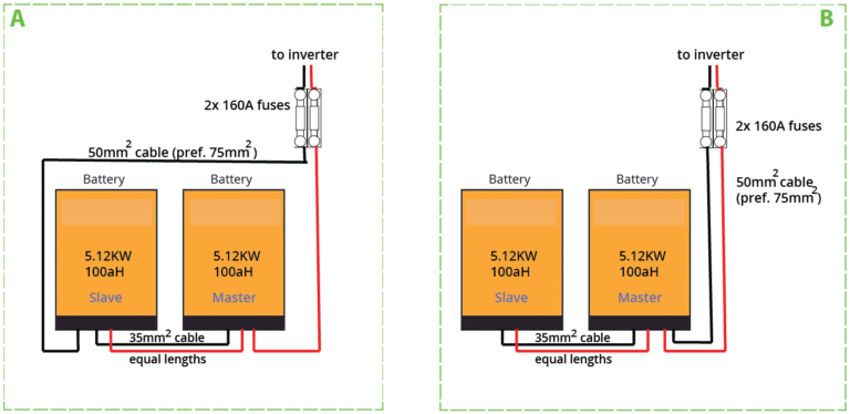
Each battery connected to a parallel busbar should normally have individual positive-branch protection.
For a series-parallel battery bank, each complete series string should have its own fuse or DC breaker before it joins the parallel busbar.
Official lithium battery installation guidance recommends fusing individual parallel batteries and fusing each positive series string in a series-parallel bank. It also warns against interconnecting series-string midpoints.
Branch protection allows one battery or string to be isolated without leaving its cable connected to the full fault current available from the remaining bank.
3. Main Battery Bank Fuse
A main fuse is installed between the combined battery bank and the inverter or DC distribution system.
Its purpose is to protect:
- The main positive cable
- The main DC distribution path
- The inverter supply circuit
- Downstream equipment under high-fault-current conditions
The main fuse does not replace individual branch fuses. A fault in one small branch cable may not draw enough current to open a much larger main fuse quickly.
4. DC-Rated Circuit Breaker or Disconnect
A DC breaker or switch-disconnector provides a safe means of isolating the battery bank during:
- Installation
- Maintenance
- Emergency shutdown
- Inverter replacement
- Battery replacement
- System troubleshooting
The device must be specifically rated for the DC voltage of the system.
An AC breaker should not be substituted unless its manufacturer clearly provides an appropriate DC rating. DC arcs are more difficult to interrupt because direct current does not pass through a natural zero-current point every half cycle.
5. Pre-Charge or Controlled Energisation
Many inverters and power conversion systems contain large capacitors on their DC input.
When the battery bank is connected directly, the capacitors may appear briefly as a very low-resistance load. This can produce:
- A visible spark
- A loud connection sound
- Breaker tripping
- BMS short-circuit protection
- Contactor damage
- Connector pitting
A pre-charge circuit limits the initial current while the inverter capacitors charge.
Depending on the equipment, pre-charge may be provided by:
- The battery’s start-up circuit
- An inverter pre-charge function
- A contactor and resistor circuit
- A manual pre-charge resistor
- A dedicated battery combiner or power distribution unit
Use only the start-up procedure approved by the battery and inverter manufacturers.
Protection for Parallel Battery Banks
In a parallel system, every battery is connected to the same positive and negative busbars.
Consider four 51.2V battery modules connected in parallel. If one branch cable is damaged, the fault may be supplied not only by the battery on that branch but also by the other three batteries through the common busbar.
This is why every battery branch requires protection close to the energy source.
A typical layout is:
Battery 1 → Branch fuse or breaker → Positive busbar
Battery 2 → Branch fuse or breaker → Positive busbar
Battery 3 → Branch fuse or breaker → Positive busbar
Battery 4 → Branch fuse or breaker → Positive busbar
The negative branches connect to the negative busbar. The main positive busbar then connects through the main protection device to the inverter.
Manufacturer guidance also recommends equal current paths, matched branch conductors and individual positive-side fusing for parallel lithium batteries.
Protection for Series Battery Banks
When batteries are connected in series, their voltages add together while the amp-hour capacity remains unchanged.
Before building a series bank, confirm that the battery model is approved for series operation. The BMS, insulation, communication system and internal switching devices must all support the resulting voltage.
Do not assume that any 12.8V battery can be connected into a 48V bank. Series limits are product-specific. For example, one manufacturer may permit four specified 12.8V batteries in series, while another model may prohibit external series connection entirely.
A series battery bank should include:
- Batteries of the same model and capacity
- Similar state of charge
- Approved series quantity
- Correct polarity between batteries
- A positive-side series-string fuse
- A main disconnect suitable for total bank voltage
- No loads connected to intermediate battery points
Connecting a 12V load to one battery inside a 48V series bank creates unequal discharge and can quickly unbalance the complete string. Use an approved DC-DC converter when a lower auxiliary voltage is required.
Protection for Series-Parallel Battery Banks
A series-parallel configuration uses several batteries in series to reach the required voltage and then connects identical series strings in parallel to increase capacity.
For example:
- Four 12.8V 100Ah batteries in series = 51.2V 100Ah
- Two identical series strings in parallel = 51.2V 200Ah
- Nominal energy = 10.24kWh
This arrangement requires careful protection because both series voltage and parallel fault current are present.
Each parallel string should have:
- The same number of batteries
- The same battery model
- The same cable size
- A similar cable path
- Its own positive fuse or breaker
- A disconnecting method
- Voltage matched to the other strings before paralleling
Do not connect the midpoint of one series string to the midpoint of another unless the battery manufacturer has designed and approved that architecture. Standard installation guidance specifically advises against interconnecting series-string midpoints.
How to Select the Branch Protection Rating
There is no universal fuse rating for every 100Ah or 200Ah LiFePO4 battery.
The correct selection depends on:
- Maximum continuous battery discharge current
- BMS overcurrent limit
- Cable ampacity
- Inverter continuous current
- Inverter surge current
- Charging current
- System voltage
- Number of parallel branches
- Ambient temperature
- Fuse time-current curve
- Manufacturer requirements
- Local electrical standards
The fuse should protect the conductor while allowing the expected operating and surge currents.
A fuse selected only according to battery capacity may be incorrect. Two 100Ah batteries can have very different BMS limits—for example, one may be designed for moderate energy storage current, while another may support a much higher discharge rate.
Fuse Versus DC Breaker
Both devices can provide overcurrent protection, but they have different characteristics.
Advantages of Fuses
- Simple construction
- Fast fault interruption
- High interrupting ratings available
- No mechanical reset mechanism
- Reliable protection when correctly selected
Advantages of DC Breakers
- Can be manually switched
- Easier system isolation
- Resettable after a non-destructive trip
- Useful for maintenance and branch control
Some systems use both:
- A high-interrupt-capacity fuse for fault protection
- A DC switch-disconnector or breaker for normal isolation
Do not select a device only by its current rating. Verify:
- DC voltage rating
- Interrupting or breaking capacity
- Polarity requirements
- Installation orientation
- Terminal temperature rating
- Compatibility with the conductor and lug
- Applicable certification
Recommended Installation Sequence
A safe general sequence is:
- Switch off the inverter and all chargers.
- Open all battery branch breakers.
- Open the main battery disconnect.
- Verify battery polarity.
- Verify individual battery or string voltage.
- Confirm voltage matching before paralleling.
- Inspect fuse ratings and cable sizes.
- Connect the negative branches.
- Connect the protected positive branches.
- Configure BMS communication.
- Close branch devices one at a time.
- Use the approved pre-charge process.
- Close the main disconnect.
- Start the inverter.
- Check current, alarms and terminal temperature.
The exact sequence must follow the manuals for the installed equipment.
Common Protection Design Mistakes
Installing Only One Main Fuse
A large main fuse may not adequately protect smaller branch conductors.
Placing the Fuse Too Far from the Battery
The unprotected cable section between the battery and fuse should be kept as short and mechanically protected as practical.
Using an AC-Only Breaker
An AC-only breaker may fail to interrupt a DC fault safely.
Selecting a Breaker by Current Rating Alone
The system voltage and prospective short-circuit current are equally important.
Treating the BMS as a Service Disconnect
The BMS is an electronic protection system, not always a visible, lockable means of isolation.
Closing All Parallel Branches Simultaneously
This can make troubleshooting difficult and may produce high equalisation current when the battery voltages are not matched.
Frequently Asked Questions
Does every parallel battery need a fuse?
Individual branch protection is strongly recommended for properly designed parallel banks. The final configuration should follow the battery manufacturer’s instructions and local installation requirements.
Should the fuse rating be lower than the BMS current rating?
Not necessarily in every installation. Fuse coordination depends on cable ampacity, expected current, time-current characteristics and equipment limits. The complete protection design should be reviewed rather than comparing only two current numbers.
Can a DC breaker replace the battery power switch?
Sometimes, provided the breaker is approved for load isolation at the system’s DC voltage and current. Not every protective breaker is suitable as a frequently operated switch.
Why does the BMS trip when the inverter starts?
Possible causes include capacitor inrush current, incorrect pre-charge procedure, reverse polarity, a short circuit, an undersized cable or an incompatible inverter.
Conclusion
A safe LiFePO4 energy storage installation uses coordinated protection rather than relying on one device.
The protection architecture should include:
- Internal BMS protection
- Individual battery or string fuses
- A main battery bank fuse
- DC-rated isolation equipment
- Correctly sized conductors
- A controlled pre-charge procedure
- Proper commissioning and documentation
For commercial, telecom, solar and off-grid projects, protection requirements should be confirmed before battery production and shipment.
When requesting a LiFePO4 battery system proposal from HIZN Lithium, provide the inverter model, nominal DC voltage, continuous power, surge power, maximum charge current, required capacity and proposed series-parallel configuration. This allows the battery, BMS, cable and protection architecture to be evaluated as one complete system.