
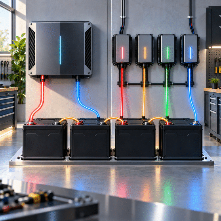
Introduction
Many solar, RV, marine and backup-power users build higher-voltage battery banks by connecting several 12.8V LiFePO4 batteries in series.
For example:
4 × 12.8V batteries in series = 51.2V nominal battery bank
This is commonly used to replace a traditional 48V lead-acid battery system.
The next question is often:
Should I charge the four batteries together with one 48V lithium charger, or should I disconnect them and charge each battery separately with a 12V charger?
Both methods can be useful in the correct situation.
However, series charging introduces an important challenge:
The charger controls the voltage of the complete battery string, while each individual battery has its own BMS and internal cells.
If the batteries become significantly imbalanced, the total string voltage can look normal while one battery reaches its charging limit much earlier than the others.
For distributors and installers supplying 12.8V lead-acid replacement LiFePO4 batteries, understanding series charging is therefore essential.
First: Confirm That the Battery Supports Series Connection
Not every 12.8V LiFePO4 battery is designed to operate in series.
Before connecting batteries, confirm the manufacturer’s specification.
Some batteries may support:
- 2 in series
- 4 in series
- A specific maximum system voltage
Other batteries may be designed for parallel connection only.
The BMS must be suitable for the voltage conditions created in a series battery bank.
Do not assume that any 12.8V LiFePO4 battery can automatically be used in a 48V system.
What Happens When Four Batteries Are Connected in Series?
When batteries are connected in series:
Voltage adds.
Capacity in amp-hours remains the same.
For example:
Four batteries: 12.8V 100Ah each
Series configuration: 51.2V 100Ah
Nominal energy: 51.2V × 100Ah = 5.12kWh
The battery bank behaves as a higher-voltage system.
However, electrically, it is still composed of four independent battery modules.
Each module has:
- Its own cells
- Its own BMS
- Its own SOC
- Its own internal resistance
This becomes important during charging.
Can One 48V/51.2V Charger Charge the Whole String?
Yes, if:
- The batteries are approved for series connection
- Charger voltage is appropriate
- Charger current is within battery limits
- All batteries have similar SOC and condition
The charger connects across the complete string.
The charging path is:
Charger Positive → Battery 1 → Battery 2 → Battery 3 → Battery 4 → Charger Negative
The same charging current flows through all four batteries.
This is one advantage of series circuits:
Current is identical through every battery.
But equal current does not automatically mean equal SOC.
Why Series Batteries Can Drift Apart
Imagine four 12.8V batteries:
- Battery A: 80% SOC
- Battery B: 78%
- Battery C: 70%
- Battery D: 79%
They are connected in series and charged together.
Because the same current flows through every battery, Battery A may reach full charge before Battery C.
When Battery A reaches its upper BMS voltage limit, its BMS may stop charging.
The whole series circuit is then interrupted.
Battery C may still be below full charge.
The charger sees that the battery string has stopped accepting current.
The customer may report:
“My 48V battery bank reaches high voltage but does not have full capacity.”
The real issue can be module-level SOC imbalance.
Total Voltage Can Hide an Imbalance
This is one of the most important concepts in series battery troubleshooting.
Suppose the total string voltage looks correct.
For example:
57V total
It is tempting to assume all four batteries are equally charged.
But the individual modules might be:
- Battery 1: 14.5V
- Battery 2: 14.4V
- Battery 3: 13.7V
- Battery 4: 14.4V
Total: 57.0V
The total looks reasonable.
But Battery 3 is clearly behaving differently.
Always measure individual battery voltages when troubleshooting a series bank.
How Should the Charger Voltage Be Calculated?
Do not choose charging voltage only from nominal system voltage.
Instead, start with the battery manufacturer’s recommended charging voltage for one battery.
Then multiply according to the series count.
For example, if the manufacturer specifies a certain charging voltage per 12.8V battery:
Total String Charging Voltage = Single-Battery Charging Voltage × Number of Batteries
If four batteries are connected in series, the charger must be configured according to the approved total voltage.
However, do not automatically use a generic online voltage such as 58.4V for every 51.2V system.
Different batteries may use different recommended settings depending on:
- Cell configuration
- BMS thresholds
- Charging strategy
- Application
Use the battery datasheet.
Charging Current Does Not Multiply in Series
This is another common misunderstanding.
Suppose each 12.8V 100Ah battery supports:
20A recommended charging current
When four batteries are connected in series, the recommended string charging current does not become:
20A × 4 = 80A
The same 20A flows through each battery.
Therefore, the series string still experiences:
20A through every module
Series connection increases voltage, not amp-hour capacity.
One 48V Charger: Main Advantages
Charging the entire series bank with one compatible charger has several benefits.
Simpler Wiring
The batteries can remain connected in their normal system configuration.
Convenient Daily Operation
No need to disconnect the battery bank every time it charges.
Suitable for Inverter Systems
A 48V-class inverter charger can manage the whole battery string automatically.
Lower Maintenance
This is usually the practical method for normal system operation.
If the battery modules remain well matched, series charging can work reliably.
When Individual Charging Becomes Useful
Individual charging can be useful when the battery modules have become noticeably unbalanced.
For example:
- One battery reaches BMS high-voltage protection early
- One battery remains at lower SOC
- Individual resting voltages differ significantly
- The series bank provides less usable capacity than expected
In this situation, the batteries may be disconnected according to the manufacturer’s procedure and charged individually.
Each battery can then be brought to a similar state before the series bank is rebuilt.
This is sometimes called:
top balancing at the module level
although it should not be confused with balancing individual cells inside a battery pack.
Why Four Separate Chargers Are Not Always Necessary
Some users think a series battery bank requires four independent chargers permanently connected to each 12.8V module.
Normally, this is not necessary for routine operation.
A correctly designed series-compatible LiFePO4 bank should be capable of charging through an appropriately configured system charger.
Separate chargers are more commonly useful for:
- Initial preparation
- Maintenance
- Correcting module SOC differences
- Troubleshooting
Permanent individual-charger arrangements can also introduce electrical-isolation issues depending on charger design.
Be Careful with Non-Isolated Chargers
This point is extremely important.
If four batteries remain connected in series, their negative terminals are not all at the same electrical potential.
Connecting several chargers whose outputs share a common ground can create a short circuit or unexpected current path.
Therefore:
Do not connect multiple individual chargers to batteries that remain in series unless the chargers and system architecture are specifically designed for this arrangement.
The safest maintenance procedure is normally to follow the battery manufacturer’s instructions and isolate the modules before individual charging where required.
Why the BMS Cannot Fully Balance Separate Battery Modules
A BMS inside a 12.8V battery typically monitors the cells within that battery.
For example, a 12.8V LiFePO4 battery normally contains four series-connected cells.
Its BMS can monitor:
- Cell 1
- Cell 2
- Cell 3
- Cell 4
But when four complete 12.8V batteries are connected in series, Battery 1’s BMS does not normally balance Battery 1 against Battery 2.
Each BMS only manages its own module.
This is different from a purpose-built 51.2V battery with one integrated BMS monitoring all 16 cells.
Series Modules vs One Integrated 51.2V Battery
Consider two approaches.
Option A
4 × 12.8V 100Ah batteries in series
Result:
51.2V 100Ah
Option B
1 × 51.2V 100Ah integrated battery
The nominal energy may be similar.
But the architecture is different.
An integrated 51.2V battery typically uses one BMS monitoring the entire 16-cell pack.
This allows:
- Pack-wide cell monitoring
- Integrated balancing
- Single SOC calculation
- Unified communication with inverter
For larger stationary ESS projects, an integrated 48V/51.2V battery is often easier to manage.
Series-connected 12.8V batteries can still be very useful for:
- Lead-acid replacement
- RV
- Marine
- Small off-grid systems
- Existing 48V battery racks
Start with Similar SOC Before Series Connection
Before connecting multiple batteries in series:
- Confirm all batteries are the same compatible model.
- Check manufacturing specification.
- Measure each battery voltage.
- Check BMS status.
- Bring batteries to a similar SOC according to the manufacturer’s procedure.
- Confirm polarity.
- Connect the series string.
- Verify total voltage before connecting the inverter.
Starting with large SOC differences makes future imbalance more likely.
New Batteries Should Also Be Matched
Even when all batteries are new, do not assume they have identical SOC.
Shipping conditions, storage time and BMS standby consumption can create small differences.
Before building a new series bank, verify each module.
This is particularly important for distributors assembling batteries that arrived from different production batches.
What Happens If One Battery Reaches High Voltage First?
Suppose Battery 2 reaches its BMS high-voltage threshold.
Its BMS may interrupt the series charging circuit.
The charger stops seeing normal current.
After the battery voltage falls slightly, the BMS may reconnect.
Charging resumes.
Then Battery 2 reaches the threshold again.
The customer may see:
charge → stop → charge → stop
This can look like charger instability.
But the root cause may be one module reaching full charge earlier than the rest.
Why Repeated BMS Cutoff Is Not a Good Balancing Strategy
Some users allow the system to repeatedly hit BMS protection, hoping the batteries will eventually equalize.
This is not the preferred method.
The BMS is a protection layer.
Normal charging should be controlled by:
- Charger voltage
- Charger current
- Correct initial battery matching
If one module repeatedly triggers protection, investigate the imbalance.
What Should You Measure?
For a series bank, record:
- Total string voltage
- Individual battery voltage
- Charger output voltage
- Charging current
- BMS alarms for every module
- Battery temperature
- Individual SOC where available
Measurements should be taken:
- Before charging
- During mid-charge
- Near full charge
- After resting
This provides much more useful information than total string voltage alone.
Example: Four 12.8V 100Ah Batteries
Suppose four compatible batteries form a:
51.2V 100Ah
bank.
At the beginning:
Battery 1: 13.2V
Battery 2: 13.2V
Battery 3: 13.2V
Battery 4: 13.2V
This looks well matched.
Near full charge:
Battery 1: 14.2V
Battery 2: 14.2V
Battery 3: 13.8V
Battery 4: 14.2V
Battery 3 is now noticeably lower.
This suggests that the modules may not be at the same SOC or may have different effective capacities.
The battery bank should be evaluated before simply increasing charger voltage.
Do Not Raise Charger Voltage to Force the Weak Battery Higher
This is a common mistake.
If one module remains low, increasing total string charging voltage can push the already-full batteries closer to their protection thresholds.
The result may be even more BMS cutoffs.
The correct approach is to identify why the module is different.
Possible causes include:
- Different SOC
- Different capacity
- Different age
- Internal cell imbalance
- BMS calibration difference
Series Battery Age Matters
Mixing:
- Old batteries
- New batteries
in one series string can create additional imbalance.
An older battery may have:
- Lower usable capacity
- Higher internal resistance
- Different voltage response
The same current flows through all series batteries, so the weakest module can limit the entire string.
For best results, use batteries that are:
- Same model
- Similar age
- Similar operating history
What About 2 × 12.8V for a 24V System?
The same principles apply.
Two 12.8V batteries in series create approximately:
25.6V nominal
A suitable charger must match the complete series voltage.
Individual battery matching remains important.
The fewer modules in series, the simpler the system becomes, but module-level imbalance can still occur.
What About 8 × 12.8V Batteries?
Do not assume that if four batteries can be connected in series, eight can also be connected.
The BMS and battery insulation may have specific maximum series-voltage requirements.
Always follow the manufacturer-specified maximum number of series-connected batteries.
For Distributors Selling Lead-Acid Replacement Batteries
Before supplying 12.8V LiFePO4 batteries for a 48V lead-acid replacement project, ask:
- How many batteries will be connected in series?
- Does the selected battery model support that number?
- What charger or inverter is currently installed?
- What is its charging voltage?
- Does it have equalization?
- What is its maximum charging current?
- Are the batteries also connected in parallel?
Series-parallel battery banks require even more careful system design.
Series-Parallel Systems
A larger system may use:
4S2P
meaning:
- Four batteries in series per string
- Two strings in parallel
If each battery is 12.8V 100Ah:
One series string:
51.2V 100Ah
Two parallel strings:
51.2V 200Ah
Now the system must manage both:
- Voltage balance within each series string
- Current sharing between parallel strings
For stationary ESS applications, a purpose-built 51.2V battery may simplify this architecture considerably.
Troubleshooting Checklist
If a series LiFePO4 battery bank does not charge normally:
- Confirm the battery model supports series use.
- Measure each individual module voltage.
- Read each BMS alarm.
- Check total charger voltage.
- Check charging current.
- Confirm equalization is disabled where required.
- Identify which battery reaches the charging limit first.
- Individually rebalance modules according to manufacturer instructions if necessary.
- Reassemble only after voltage and SOC conditions are suitable.
Conclusion
Four 12.8V LiFePO4 batteries can form a practical 51.2V battery bank—but only when the battery model is designed to support series operation.
For normal use, a correctly configured 48V/51.2V-class charger can charge the complete series string.
Individual 12V charging is mainly useful for:
- Preparation
- Maintenance
- Correcting module imbalance
- Troubleshooting
The most important point is that total string voltage cannot reveal every module-level problem.
Monitor the individual batteries, not only the combined voltage.
HIZN supplies 12.8V LiFePO4 lead-acid replacement batteries as well as integrated 25.6V, 48V and 51.2V energy storage solutions for solar, RV, marine and backup applications.
If you plan to build a series LiFePO4 battery bank, send us the battery quantity, inverter/charger model and required system voltage. We can help confirm whether a series configuration or an integrated higher-voltage battery is more suitable.