
Introduction
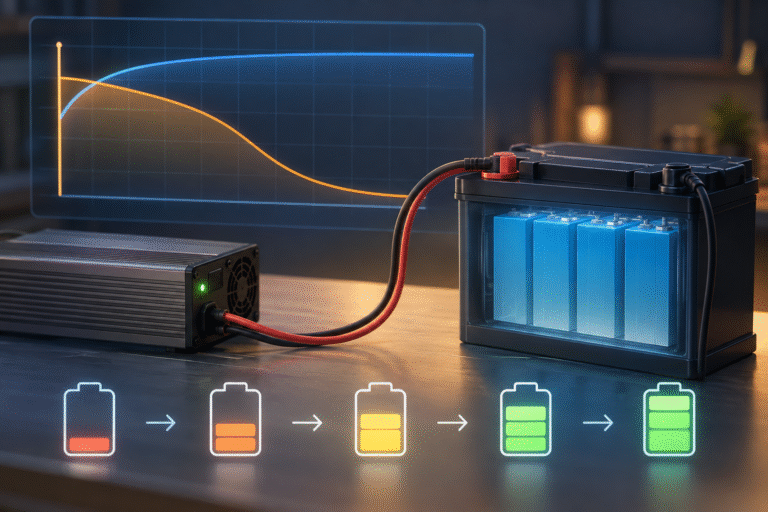
A LiFePO4 battery charges at 80A.
Later it drops to 50A.
Then 20A.
Near 100% SOC, the charging current may fall to only a few amps.
The customer immediately asks:
“Why did my charger become slower?”
Or:
“Is the BMS limiting the battery because something is wrong?”
Not necessarily.
In many LiFePO4 systems, a reduction in charging current near the top of charge is completely normal.
Charging current can decrease because of:
- Constant-voltage charging behavior
- BMS charge-current limits
- Cell balancing
- One cell approaching its upper voltage threshold
- Inverter charging strategy
- Reduced solar availability
- Temperature
The important task is to distinguish between:
normal charge-current taper and abnormal early current limitation
LiFePO4 Charging Is Often Described as CC/CV
A common charging method is:
CC/CV
meaning:
Constant Current / Constant Voltage
During the first part of charging, the charger attempts to provide a relatively constant current.
As battery voltage reaches the configured charging-voltage limit, the charger stops increasing voltage.
It then holds approximately the target voltage.
At that point, charging current naturally begins to decrease.
This is the constant-voltage phase.
Example of CC/CV Charging
Imagine a LiFePO4 battery is being charged at: 50A
During most of the charging process: Current ≈ 50A
Battery voltage gradually rises.
Near the upper charging voltage, the charger can no longer continue raising battery voltage while maintaining 50A.
Instead, it holds the voltage.
Current may then fall: 50A → 35A → 20A → 10A → lower
This behavior does not automatically indicate reduced charger performance.
It may simply mean the battery is approaching the configured charging limit.
LiFePO4 Has a Relatively Flat Voltage Curve
LiFePO4 chemistry has a characteristic voltage curve.
Through much of the SOC range, cell voltage changes relatively slowly.
Near the upper end of charge, however, cell voltage begins to rise more quickly.
This creates what is sometimes called the: upper voltage knee
At this point, adding a relatively small amount of charge can produce a larger voltage increase.
That is one reason current often needs to reduce near full charge.
Pack Voltage Is Only Part of the Story
Consider a 16-cell LiFePO4 battery.
The total pack voltage may still look normal.
However, one cell may be slightly higher than the others.
For example:
15 cells: approximately similar voltage
1 cell: approaching the BMS high-voltage limit
The BMS may request lower charging current even though the total pack voltage does not look unusually high.
This protects the highest cell.
One Cell Can Limit the Whole Battery
This is a key concept.
A 51.2V battery contains multiple cells in series.
The battery is only as balanced as those cells.
Suppose most cells are below their upper charging limit, but one cell reaches the threshold early.
The BMS cannot simply continue pushing full current until the other cells catch up.
It may:
- Reduce allowed charging current
- Trigger balancing
- Stop charging temporarily
The customer may see charging current falling before displayed SOC reaches 100%.
Cell Balancing Often Happens Near the Top
Many LiFePO4 BMS systems perform passive balancing primarily at higher cell voltages.
Passive balancing usually works by allowing a small amount of energy to bypass or dissipate from higher-voltage cells.
This balancing current is typically much smaller than normal battery charging current.
For example, the battery may normally charge at tens of amps, while cell balancing works at a much smaller current.
Therefore, near full charge, the system may reduce charging current to allow the BMS more time to manage cell differences.
Why Fast Charging Can Expose Imbalance
Suppose the battery is charged at high current.
Most cells rise together.
One slightly higher cell reaches the upper-voltage region first.
At high charging current, its voltage can rise quickly.
The BMS reacts by limiting or stopping charging.
If charging current is reduced, the cell voltage may relax and the battery can continue charging more gradually.
This is why a battery that repeatedly stops near full SOC may behave better at a lower finishing current.
Is Current Taper Always Normal?
No.
The key question is:
At what SOC and under what conditions does the current drop?
Normal taper usually occurs near the upper part of the charging process.
If charging current falls dramatically at:
- 20% SOC
- 30% SOC
- 40% SOC
there may be another limitation.
Possible causes include:
- Inverter setting
- Solar shortage
- BMS temperature limit
- Communication error
- Charger overheating
- Grid-power limitation
- One abnormal cell
The charging data should be reviewed.
Solar Power Can Make Current Drop for a Completely Different Reason
Imagine the battery is only 60% full.
Charging current falls from: 80A → 30A
Is the battery limiting current?
Maybe not.
A cloud may have reduced solar production.
Or household loads may have increased.
Therefore, when charging current drops, compare:
- PV power
- Load power
- Grid power
- Battery current
at the same moment.
Never diagnose the battery from charging current alone.
Example: Morning vs Afternoon
Morning:
PV power = 7kW
Load = 2kW
Battery receives substantial charging power.
Afternoon:
PV power = 4kW
Load = 3kW
Much less power remains for the battery.
Charging current falls.
The battery has not necessarily changed its charging behavior.
The energy available to it has changed.
BMS Communication Can Intentionally Reduce Current
In a closed-loop energy storage system, the battery may communicate with the inverter through:
- CAN
- RS485
The BMS can send a parameter such as:
Charge Current Limit
or
CCL
The inverter follows this value.
For example:
At moderate SOC: BMS allows 100A
Near high cell voltage: BMS reduces to 50A
Later: BMS reduces to 20A
This is intelligent control, not necessarily a fault.
Why Closed-Loop Control Is Better Than Hard Shutdown
Without communication, the inverter may continue charging at the configured current until the BMS protection threshold is reached.
Then the BMS abruptly disconnects charging.
With closed-loop communication, the battery can request a lower current first.
This can produce smoother charging and fewer hard BMS cutoffs.
For larger stationary ESS systems, this is one advantage of CAN/RS485 integration.
Temperature Can Reduce the Charging Current
Battery charging capability is also temperature-dependent.
If the battery becomes too hot, the BMS may reduce charging current.
Similarly, cold conditions can lead to:
- Reduced charging current
- Complete low-temperature charging protection
Therefore, if current falls unexpectedly, check battery temperature.
Do not assume every current limit is SOC-related.
Inverter Temperature Matters Too
The battery may be perfectly cool while the inverter is hot.
Many hybrid inverters reduce charging or output power when internal temperature rises.
This is called: thermal derating
A customer may see charging current decrease every afternoon during the hottest part of the day.
Possible causes include:
- Battery temperature
- Inverter temperature
- Both
Check both devices.
The Charger Itself May Have Reached Its Voltage Limit
Suppose the charger is configured for a specific maximum voltage.
As the battery reaches that voltage, the charger cannot continue increasing voltage.
To prevent exceeding the setpoint, current falls.
This is expected CC/CV behavior.
Increasing the voltage setting just to maintain high current is not the correct solution.
Charging voltage should remain within the battery manufacturer’s specification.
Why the Last 5% Can Take Longer Than Expected
Customers sometimes notice:
20% to 90% charges quickly.
But: 90% to 100% takes much longer.
This can happen because:
- Current begins to taper
- Cells begin balancing
- BMS reduces charge-current limit
- The battery approaches constant-voltage operation
Therefore, charging time is not always linear.
If 20% of capacity takes one hour at high charging power, the final 20% may not take exactly the same time.
Do You Need to Wait for Current to Reach Zero?
Not necessarily.
The charging termination strategy depends on:
- Charger
- BMS
- Battery manufacturer
- Inverter communication
Some systems define full charge using:
- Voltage
- Current
- SOC
- Time
- Combination of conditions
A battery display may show 100% while a small charging current continues.
This can be normal.
Why Current Sometimes Rises Again
You may observe: 50A → 10A → 25A
near the upper charging range.
Possible explanation:
A high-voltage cell triggered temporary current reduction.
The cell relaxed.
Balancing reduced the difference.
The BMS then allowed more current again.
Solar conditions and loads may also cause current to fluctuate.
Small variations are not automatically a fault.
What Is an Abnormal Current Drop?
Investigate when:
- Current drops very early in the charge cycle
- BMS reports an alarm
- One cell is much higher than others
- Battery temperature is abnormal
- Current repeatedly goes from high to zero
- Charging never completes
- Usable capacity is noticeably reduced
The root cause should be identified before changing charger settings.
Example: 51.2V 314Ah Battery
Consider a 51.2V 314Ah battery.
At a moderate charging rate, the current may remain relatively stable through much of the cycle.
Near the upper SOC region, the system may gradually reduce current.
If the BMS indicates:
- Normal cell voltages
- No temperature alarm
- Normal communication
- Increasing SOC
then lower finishing current may be completely normal.
Now imagine the same battery begins limiting charging at 40% SOC.
That deserves investigation.
Cell Voltage Difference Is More Useful Than SOC Alone
When troubleshooting near-full charging, check:
maximum cell voltage
minimum cell voltage
and
cell voltage difference
If the difference becomes large near high SOC, balancing may be the limiting factor.
SOC alone cannot show this.
Why Cell Difference Looks Larger Near Full Charge
Because LiFePO4 voltage rises more sharply near the upper SOC region, small differences in actual cell capacity can become more visible.
At mid-SOC, cells may show very similar voltages.
Near full charge, one cell may rise earlier.
This does not automatically mean the cell is defective.
However, persistent or excessive imbalance should be evaluated.
Do Not Raise Charging Voltage to Force More Current
When users see tapering current, a common reaction is:
“I will increase charging voltage.”
This may push the highest cells closer to BMS protection.
The correct voltage should follow the battery specification.
If charging current falls normally near full SOC, no correction may be required.
Do Not Disable BMS Current Limiting
If the battery communicates a lower charging-current limit, do not attempt to override it simply to maintain maximum charging speed.
The BMS may be responding to:
- Cell voltage
- Temperature
- Internal protection logic
First determine why the limit changed.
How to Diagnose a Charging-Current Drop
Record the following at the same time:
Battery
- SOC
- Pack voltage
- Charge current
- Maximum cell voltage
- Minimum cell voltage
- Cell-voltage difference
- Temperature
- BMS charge-current limit
- Alarm status
Inverter
- PV power
- Load power
- Grid power
- Charging-current setting
- Battery charging power
- Temperature
This data can usually identify whether the limitation comes from:
- Battery
- Inverter
- Energy source
Practical Example
Suppose:
Battery SOC = 95%
PV available = strong
Load = low
BMS charge limit = 20A
Maximum cell voltage = high but within normal range
No alarm
This likely indicates normal finishing behavior.
Another example:
Battery SOC = 45%
BMS charge limit = 20A
Battery temperature = high
The likely cause may be thermal derating.
The same charging current can therefore have completely different explanations.
For Distributors: Ask Customers for BMS Screenshots
When a customer says:
“Your battery is only charging at 20A.”
Do not immediately conclude the battery is faulty.
Ask for:
- Battery SOC
- BMS cell-voltage screen
- Battery temperature
- BMS alarm page
- Inverter power-flow screen
- Charging-current setting
A screenshot showing only the current number is rarely enough.
Does Lower Current Mean Lower Battery Capacity?
No.
Charging current describes:
how quickly energy is entering the battery
Battery capacity describes:
how much energy the battery can store
These are different.
A healthy 20kWh battery can charge at 20A or 100A depending on system conditions.
Lower current does not automatically mean capacity loss.
Should You Always Charge at the Maximum Current Until 100%?
No.
The highest possible charging speed is not always the best operating strategy.
A properly controlled system may intentionally reduce current near full charge to:
- Protect cells
- Allow balancing
- Control voltage
- Manage temperature
The goal is reliable charging, not maintaining maximum current at every SOC.
Conclusion
A LiFePO4 battery charging current often decreases as the battery approaches full charge.
This can be caused by normal:
- CC/CV charging behavior
- BMS current control
- Cell balancing
- High cell voltage management
However, current reduction at low or middle SOC may indicate another limitation such as:
- Insufficient solar power
- Heavy loads
- Temperature
- Inverter limits
- Cell imbalance
The correct diagnosis requires looking at the complete system.
HIZN supplies LiFePO4 energy storage batteries with intelligent BMS, CAN/RS485 communication and multiple capacities for residential, commercial and off-grid applications.
If your LiFePO4 battery charging current is lower than expected, send us the battery model, SOC, cell-voltage data, inverter model and charging screen. We can help determine whether the behavior is normal charge taper or a system limitation.