
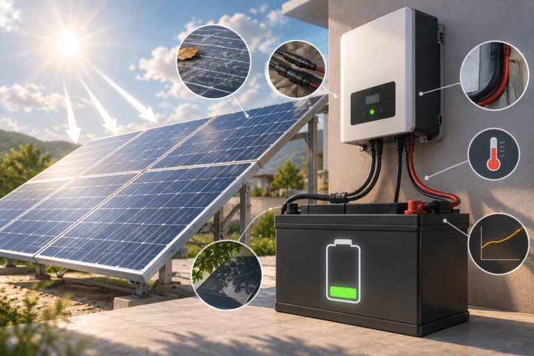
Introduction
A solar installer checks the system and sees:
- 6kW of solar panels installed
- A 51.2V LiFePO4 battery
- Plenty of sunlight
- Battery SOC below 50%
Yet the battery is charging at only a few hundred watts—or not charging at all.
The first reaction is often:
“The battery must have a charging problem.”
But solar-panel wattage alone does not determine whether a battery can be charged correctly.
For an MPPT solar charger or hybrid inverter to transfer PV energy into a LiFePO4 battery, the PV array must operate within the charger’s required:
- Voltage range
- Current range
- Power range
A system can have more than enough solar watts while still having the wrong solar voltage.
This is particularly important when designing PV strings for 48V and 51.2V LiFePO4 energy storage systems.
Solar Panel Watts and Volts Are Different Problems
Consider a solar panel rated at:
590W
That power rating does not tell us whether one panel can directly charge a 51.2V battery through a particular MPPT.
A panel datasheet normally includes values such as:
- Maximum power: Pmax
- Voltage at maximum power: Vmp
- Current at maximum power: Imp
- Open-circuit voltage: Voc
- Short-circuit current: Isc
For MPPT design, voltage and current matter just as much as total wattage.
Two arrays can both contain 6kW of panels but have completely different electrical characteristics depending on how the panels are connected.
Series Connection Raises PV Voltage
When solar panels are connected in series:
Voltage adds
while string current remains approximately the same.
For example, if each panel has a Vmp of approximately 40V:
One Panel
Vmp ≈ 40V
Two Panels in Series
Vmp ≈ 80V
Four Panels in Series
Vmp ≈ 160V
The actual values depend on the panel.
This allows installers to build a PV string voltage suitable for the MPPT input of the inverter.
Parallel Connection Increases Current
When identical PV strings are connected in parallel:
Current adds
while voltage remains approximately the same.
For example:
String 1: 160V, 12A
String 2: 160V, 12A
Connected in parallel:
approximately: 160V, 24A
This is why PV system design must check both:
- Maximum voltage
- Maximum current
Adding panels incorrectly can exceed either limit.
The MPPT Has an Operating Voltage Window
A hybrid inverter may specify something such as:
- Maximum PV voltage
- MPPT voltage range
- Rated MPPT voltage
- PV startup voltage
These numbers are not interchangeable.
Maximum PV Voltage
The solar array must never exceed this voltage under the specified conditions.
MPPT Operating Range
The inverter tracks solar power efficiently only within this range.
Startup Voltage
The PV array may need to exceed a certain voltage before the inverter starts its solar charger.
A PV array that falls below the MPPT operating range may produce sunlight and measurable voltage but still fail to charge the battery effectively.
Why a 51.2V Battery Makes This Important
A 51.2V LiFePO4 battery does not charge at exactly 51.2V.
Its charging voltage is higher than nominal voltage.
Therefore, the MPPT must be able to convert available PV voltage into the required battery charging voltage.
For many inverter architectures, the PV string is deliberately designed at a substantially higher voltage than the battery bank.
For example, a 51.2V battery system may use PV strings operating at:
- 100V+
- 200V+
- 300V+
depending entirely on inverter design.
There is no universal PV voltage for a 51.2V battery.
The inverter MPPT specification determines the correct string configuration.
A Common Mistake: Too Few Panels in Series
Suppose a customer expands a solar system.
Instead of reviewing the inverter’s MPPT specification, they connect panels based only on wattage.
The array has sufficient theoretical power but too few panels in series.
At strong midday sunlight the system may just reach the required MPPT voltage.
But during:
- Morning
- Late afternoon
- Cloudy conditions
- High panel temperature
PV operating voltage may fall below the useful range.
The customer then experiences:
- Charging starting late
- Charging stopping early
- Low charging power
- Unstable MPPT operation
The battery may be completely normal.
Why Panel Temperature Changes Voltage
Solar-panel voltage changes with cell temperature.
This is an important PV design principle.
Generally:
Higher panel temperature → lower panel voltage
and:
Lower panel temperature → higher panel voltage
This creates two different design risks.
Hot Weather
PV operating voltage can fall.
A marginal string may drop below the ideal MPPT operating range.
Cold Weather
Open-circuit voltage rises.
The string may approach or exceed the inverter’s maximum PV input voltage if the system was designed without sufficient margin.
Therefore, PV string design must consider local temperature extremes.
Hot Climates Need Special Attention
This issue is particularly relevant in:
- Middle East
- Africa
- Southeast Asia
- Tropical regions
A rooftop solar panel can become much hotter than the surrounding air.
If the PV string voltage is already close to the lower MPPT limit, high panel temperature can reduce it further.
The result may be disappointing charging performance even during strong sunshine.
The customer may say:
“It is extremely sunny, but battery charging power is low.”
Strong sunlight does not automatically mean optimal panel voltage.
Morning Charging Can Reveal a Marginal String Design
Consider an inverter that requires a certain PV startup voltage.
Early in the morning:
- Solar irradiance begins increasing
- Panels produce voltage
- Available current is still low
The inverter may remain in standby until its startup conditions are satisfied.
With a correctly designed string, charging begins normally.
With a marginal string, the inverter may repeatedly:
start → detect insufficient PV conditions → stop → retry
The user may interpret this as unstable battery charging.
But the issue is on the PV side.
MPPT Voltage Is Not the Same as Battery Voltage
Another common misunderstanding is:
“My battery is 51.2V, so a 60V solar array should be enough.”
Not necessarily.
The required PV voltage depends on the inverter topology.
Some MPPT chargers are designed for relatively low PV voltage.
Others require high-voltage PV strings.
A hybrid inverter with an MPPT range of hundreds of volts cannot be correctly operated from a 60V array simply because the battery is around 51.2V.
Always design the PV array according to the inverter datasheet.
Too Much PV Voltage Is Also Dangerous
If low voltage is bad, should installers simply add more panels in series?
No.
The inverter has a maximum PV input voltage.
This limit must not be exceeded.
The most dangerous condition may occur on a cold, bright morning when panel open-circuit voltage is higher than its value at standard test conditions.
PV string design should therefore calculate:
Maximum possible cold-weather Voc
not only nominal Vmp.
Exceeding the inverter’s maximum PV voltage can damage power electronics.
Do Not Confuse MPPT Voltage Range with Maximum Voltage
Suppose an inverter specification contains:
- Maximum PV voltage: 500V
- MPPT range: 120–450V
A PV string operating at 90V does not become acceptable simply because it is below 500V.
It may still be below the MPPT operating range.
Likewise, designing a string to operate continuously near 500V provides insufficient safety margin.
Each specification has a different purpose.
Current Limits Matter Too
PV voltage may be perfect while current exceeds the inverter input specification.
This can happen when installers add too many parallel strings.
Check:
- Maximum MPPT input current
- Maximum short-circuit current
- Number of MPPT inputs
- Current allowed per input
Modern high-power solar panels can have substantial operating current.
An inverter designed for older, lower-current modules may not automatically accept multiple modern high-current strings on one MPPT.
More Solar Panels Do Not Always Mean More Battery Charging
Suppose:
PV array available power: 10kW
Battery charging limit: 5kW
House load: 2kW
The battery may receive only about 5kW even when enough PV energy is available.
The remaining solar power may:
- Supply loads
- Export to grid
- Be curtailed
depending on system configuration.
Therefore, after confirming the PV voltage is correct, also check:
- MPPT power limit
- Inverter battery-charge limit
- BMS charge-current limit
Example: Battery Charges Well at Noon but Poorly in the Morning
This pattern provides a useful clue.
Possible causes include:
- PV string voltage close to the MPPT minimum
- Shading on one or more panels
- Incorrect string configuration
- Inverter startup-voltage requirement
- Insufficient morning solar power
If the battery were the main problem, charging behavior would not necessarily follow the same time-of-day pattern every day.
Compare PV voltage throughout the day.
Example: Battery Charging Suddenly Stops on a Very Hot Afternoon
Possible sequence:
- Solar panels become hotter.
- PV voltage decreases.
- String voltage approaches the MPPT lower limit.
- Inverter reduces or loses MPPT operation.
- Battery charging power falls.
At the same time, inverter thermal derating may also occur.
Therefore, record both:
- PV voltage
- Inverter temperature
when diagnosing hot-afternoon charging problems.
Shading Can Affect String Voltage and Power
A PV string is sensitive to shading.
Depending on panel and bypass-diode behavior, partial shading can significantly reduce usable string power.
Examples include:
- Tree shadow
- Chimney
- Antenna
- Nearby building
- Dirt concentrated on one module
The battery cannot distinguish whether the missing charging power comes from:
- Clouds
- shading
- MPPT limits
It simply receives less energy.
Check Each MPPT Separately
Many hybrid inverters have:
- MPPT 1
- MPPT 2
- MPPT 3
If total charging is lower than expected, review each input individually.
For example:
MPPT 1: 320V, 8A
MPPT 2: 110V, 0A
The second array may have:
- Open string
- Incorrect breaker state
- Loose MC4
- Wrong polarity
- Voltage outside MPPT range
Looking only at total PV power can hide the problem.
PV String Voltage Testing
During commissioning, record:
- String open-circuit voltage
- Operating voltage under MPPT
- String current
- Individual MPPT power
Compare these values with:
- Panel datasheet
- Number of panels in series
- Number of strings in parallel
- Inverter specification
Do not rely only on the inverter displaying:
“PV connected.”
A connected PV array can still be incorrectly designed.
Example Calculation
Assume one solar panel has:
Vmp = 41V
Voc = 49V
Four panels in series would give approximately:
Vmp:
41 × 4 = 164V
Voc at standard conditions:
49 × 4 = 196V
Six panels:
Vmp ≈ 246V
Voc ≈ 294V
These are simplified values.
A professional string calculation must also include:
- Temperature coefficient
- Minimum site temperature
- Maximum site temperature
- Inverter voltage limits
The example simply shows why panel quantity in series changes charging-system behavior.
Battery Charging Troubleshooting: Check the PV Side First
If a solar battery is charging slowly, collect:
PV Information
- Panel model
- Number of panels
- Series configuration
- Parallel strings
- PV voltage
- PV current
- PV power
Inverter Information
- MPPT range
- Startup voltage
- Maximum PV voltage
- Maximum PV current
- Maximum battery charging power
Battery Information
- SOC
- Voltage
- Current
- BMS charge limit
- Temperature
- Alarm status
This separates the problem into three layers:
PV → inverter → battery
Do Not Increase Battery Charging Voltage to Fix Low PV Input
If insufficient PV energy reaches the inverter, changing the battery charging-voltage setting does not solve the PV problem.
Likewise, increasing the BMS current limit cannot create solar energy that is not available.
Correct the actual bottleneck.
For Distributors and EPC Contractors
Before quoting a solar battery project, request:
- Solar-panel model
- Quantity
- Vmp
- Voc
- Imp
- Inverter model
- Number of MPPTs
- Proposed string arrangement
- Battery voltage
- Battery capacity
This allows the PV system and battery charging architecture to be evaluated together.
It is especially important for 48V/51.2V off-grid systems where customers may purchase panels, inverter and batteries from different suppliers.
Common Mistakes
Avoid:
- Selecting PV strings based only on total watts
- Ignoring inverter startup voltage
- Operating close to the bottom of the MPPT range
- Ignoring cold-weather Voc
- Adding too many parallel strings
- Mixing mismatched panels on one string
- Assuming battery voltage determines correct PV voltage
- Blaming the battery before checking PV input data
Conclusion
A solar array can have enough installed wattage and still fail to charge a LiFePO4 battery effectively.
The solar array must also provide the correct:
- Voltage
- Current
- String configuration
for the inverter’s MPPT.
When solar charging is unexpectedly weak, check the complete path:
PV array → MPPT → inverter charger → BMS → battery
rather than focusing only on battery SOC.
HIZN supplies 12.8V, 25.6V, 48V and 51.2V LiFePO4 batteries for solar energy storage, residential ESS, telecom and off-grid projects.
For a solar-storage project, send us your panel specification, panel quantity, string configuration, inverter model and required battery capacity. We can help review whether the proposed charging system is properly matched before installation.