
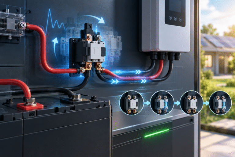
Why Large Inverters Create an Inrush Current
Inside many inverters are large: DC-link capacitors
When the inverter is disconnected, these capacitors may have little or no voltage.
Now imagine connecting a: 51.2V battery directly to them.
For a very short moment, the capacitors look almost like a low-resistance load.
A large current can flow as they charge.
This is called: inrush current
Inrush Current Can Be Much Higher Than Normal Load Current
Suppose the inverter normally draws: 100A at high load.
The instantaneous connection current during capacitor charging can be much higher than the normal operating current.
Even though the event lasts only a short time, it may trigger:
- BMS overcurrent protection
- Fuse stress
- Contactor arcing
- Connector sparks
This is why large ESS batteries often use precharge circuits.
What Is a Precharge Circuit?
A precharge circuit allows the inverter’s DC capacitors to charge gradually before the main contactor closes.
A simplified sequence is:
- Battery detects startup request.
- Precharge path closes.
- Current flows through a resistor.
- Inverter DC bus voltage rises gradually.
- Voltage difference becomes small.
- Main contactor closes.
- Precharge path is released.
This avoids a large instantaneous current.
What Does the Precharge Resistor Do?
The resistor limits current during capacitor charging.
Without it:
Battery → nearly empty capacitor
can create extremely high inrush.
With the resistor:
Battery → resistor → capacitor
current is controlled.
The resistor is only used briefly.
It is not intended to carry full inverter current during normal operation.
Why Does the Main Contactor Click Off Again?
Several different conditions can cause this.
1. Precharge Failed
The inverter DC-bus voltage did not rise sufficiently.
2. Inrush Current Was Too High
The BMS detected overcurrent.
3. Voltage Difference Remained Too Large
The BMS decided it was unsafe to close the main contactor.
4. Inverter Immediately Drew Heavy Load
The inverter started with connected loads.
5. Charger Voltage Was Already Too Different
An external charger may have created an unexpected DC-bus voltage.
6. Communication Did Not Complete
Some intelligent systems require a communication handshake before allowing normal operation.
A Typical Failed Startup Cycle
The process may look like this:
- Battery main contactor closes.
- Large inrush current flows.
- BMS detects overcurrent.
- Contactor opens.
- DC bus discharges.
- BMS recovery timer expires.
- Contactor closes again.
- Same event repeats.
The result is: click → click → click
every few seconds.
Do Not Let the System Cycle Repeatedly
Repeated contactor cycling can stress:
- Contactor contacts
- Precharge resistor
- Fuse
- DC connectors
- BMS
If the system repeatedly fails startup, switch it off and investigate.
Do not leave it clicking for hours.
Contactors Are Different from MOSFET-Based BMS Systems
Smaller LiFePO4 batteries often use MOSFETs for charging/discharging control.
Larger energy storage cabinets may use:
- Mechanical contactors
- Relays
- Precharge circuits
Mechanical contactors make audible sounds.
A click by itself is not abnormal.
A properly functioning battery may click once during startup and once during shutdown.
Repeated rapid cycling is different.
The Inverter Should Usually Start Without Heavy Loads
Imagine the inverter has:
- Air conditioner
- Pump
- Refrigerator
- Large motor
already connected.
When the main battery contactor closes, the inverter may:
- Charge its internal capacitors.
- Start power electronics.
- Immediately attempt to supply large loads.
The battery sees a much larger current event.
For commissioning, it may be useful to:
- Disconnect major loads
- Start battery
- Start inverter
- Confirm stable DC bus
- Add loads gradually
according to equipment procedures.
Why Precharge Is Particularly Important for High-Power Inverters
A: 1kW inverter
and a: 15kW inverter
do not necessarily present the same DC-link capacitance or startup behavior.
Large systems commonly have:
- Larger capacitors
- Higher power electronics
- Multiple inverter modules
As system power increases, precharge design becomes increasingly important.
Parallel Inverters Make It More Important
Suppose three inverters share one battery bank.
Each inverter contains DC-link capacitors.
If all three connect simultaneously, the battery may need to precharge a much larger combined capacitance.
A precharge circuit designed for one inverter may not automatically work correctly with three.
System designers should confirm compatibility.
Charger Connection Can Also Create Inrush
A charger itself may contain large input or output capacitors.
If the charger is connected directly to the battery while its DC side is discharged, a transient current can occur.
The exact behavior depends on charger architecture.
For large ESS installations, both:
- inverter
- charger
should be considered in DC-bus startup design.
Voltage Difference Is a Key Precharge Parameter
Before the main contactor closes, the BMS may compare:
Battery voltage with DC-bus voltage
Example:
Battery = 52V
DC bus = 5V
Difference = 47V
Closing the main contactor now could create severe inrush.
After precharge:
Battery = 52V
DC bus = 49V
Difference = 3V
Closing is much safer.
Exact thresholds depend on the system.
What If the Precharge Resistor Is Too Large?
A larger resistor limits current strongly.
But it also charges the capacitors more slowly.
If the BMS allows only a short precharge time, the DC bus may fail to reach the required voltage before the timeout.
Result:
Precharge timeout
The contactor never closes.
What If the Precharge Resistor Is Too Small?
A smaller resistor charges capacitors faster.
But current becomes higher.
This can stress:
- Precharge relay
- Resistor
- Battery
The resistor must be engineered for:
- Resistance
- Pulse energy
- Power
- Precharge time
This is not simply a matter of choosing the lowest resistance possible.
Why the Precharge Resistor Can Become Hot
During precharge, electrical energy is dissipated as heat in the resistor.
Normally, precharge lasts only briefly.
If the system repeatedly retries:
precharge → fail → precharge → fail
the resistor can heat significantly.
Repeated failed startup should therefore be stopped and investigated.
A Failed Precharge Relay Can Cause Similar Symptoms
Possible hardware issues include:
- Precharge relay not closing
- Main contactor not closing
- Welded contact
- Loose connection
- Damaged resistor
The BMS may log an error such as:
- Precharge fault
- Contactor fault
- Bus-voltage error
Alarm history is extremely useful.
Charger Voltage Mismatch Can Cause Contactor Cycling
Imagine an external charger holds the DC bus at: 58V
while the battery is currently: 52V
The BMS attempts to connect.
The voltage difference may exceed the permitted threshold.
The contactor may refuse to close or may open immediately.
Before connecting multiple DC devices, ensure their voltage ranges and startup sequences are compatible.
BMS High-Voltage Protection Can Also Sound Like Chattering
Not all contactor cycling is a precharge problem.
Another scenario:
- Battery charges.
- One cell reaches high-voltage protection.
- BMS opens charging contactor.
- Cell voltage relaxes.
- BMS reconnects.
- Charging resumes.
- High-voltage protection occurs again.
This can also produce repeated clicking.
Check whether cycling occurs:
- only at startup
or
- during high-SOC charging
The timing provides an important clue.
Overcurrent During Inverter Startup
Suppose contactor cycling occurs only when:
inverter ON
but battery remains stable when the inverter is disconnected.
This suggests investigating:
- Inverter inrush
- Precharge
- DC-bus capacitance
- Startup load
- Cable short circuit
Do not immediately blame battery cells.
If It Happens Only When the Charger Starts
If the battery powers loads normally but contactor cycles when charging begins, check:
- Charger output voltage
- Charging current
- Cell overvoltage
- Communication settings
- Charger DC-bus behavior
The diagnostic path is different.
BMS Logs Are Extremely Valuable
Ask for error history containing items such as:
- Charge overcurrent
- Discharge overcurrent
- Short circuit
- Precharge timeout
- Contactor fault
- Cell overvoltage
- Pack overvoltage
The audible click tells you that the contactor moved.
The event log tells you why.
DC Cable Resistance Also Affects Startup
Poor DC connections can create significant voltage drop during startup.
The BMS may close the contactor.
Current rises.
Voltage suddenly falls.
The BMS detects:
- undervoltage
- abnormal bus condition
and opens again.
Inspect:
- Cable size
- Cable lugs
- Breakers
- Busbars
- Fuse holders
Long DC Cables Can Make Precharge More Complicated
Long cables add:
- Resistance
- Inductance
For high-power battery systems, the inverter and battery are generally best located with appropriately short and correctly sized DC connections.
Do not place the battery tens of meters from the inverter without engineering the DC system carefully.
Parallel Batteries Need Coordinated Contactors
In modular ESS systems, several batteries may each contain internal contactors.
A master BMS may sequence them.
If modules close at significantly different times, one battery could temporarily carry disproportionate current.
Correct:
- addressing
- communication
- master/slave setup
is therefore important.
One Battery Clicking While Others Stay Connected
In a parallel battery bank, if one module repeatedly clicks while others operate normally, check that module for:
- BMS alarm
- Contact resistance
- Precharge fault
- Different SOC
- Communication loss
- Temperature
- Cell voltage
Do not assume the whole bank has the same condition.
Precharge and Large 51.2V Battery Cabinets
Floor-standing or rack ESS batteries often use larger BMS architectures because they support:
- 100A
- 200A
- higher power
At these currents, controlled connection becomes important.
For example, a: 51.2V 400Ah battery
can supply substantial power.
Connecting it to a large inverter without proper precharge can produce severe transient current.
Commissioning Sequence Matters
A typical commissioning logic may include:
- Verify battery voltage.
- Verify polarity.
- Open large AC loads.
- Connect battery DC protection.
- Power battery/BMS.
- Allow precharge sequence.
- Confirm contactor closed.
- Start inverter.
- Confirm communication.
- Add loads gradually.
Actual sequence must follow the battery and inverter manuals.
Never Bypass the Precharge System
If the main contactor refuses to close, do not bypass:
- Precharge resistor
- Contactors
- BMS control
A failed precharge sequence may be protecting the system from very high current.
Find the reason.
Do Not Manually Force the Contactor Closed
Mechanically or electrically forcing a contactor closed can defeat:
- Overcurrent protection
- Voltage-difference protection
- Precharge logic
This can damage:
- inverter
- BMS
- battery
- cables
Use approved diagnostic procedures.
Troubleshooting Checklist
If the battery contactor repeatedly cycles:
- Determine when it happens.
- Read BMS alarm history.
- Check battery voltage.
- Check inverter DC-bus voltage.
- Disconnect large loads.
- Verify precharge sequence.
- Check charger output voltage.
- Inspect DC cables and breakers.
- Check CAN/RS485 communication.
- Confirm inverter compatibility.
Identify the Timing
Immediately During Startup
Likely areas:
- Inrush
- precharge
- inverter DC bus
Only During Charging Near 100% SOC
Likely areas:
- cell overvoltage
- charge settings
Only Under Large Load
Likely areas:
- discharge overcurrent
- voltage sag
- cable resistance
Randomly During Operation
Investigate:
- communication
- temperature
- loose connections
- BMS hardware
This simple classification can save substantial troubleshooting time.
Information Distributors Should Request
When customers report repeated clicking, ask for:
- Battery model
- Inverter model
- Number of inverters
- Battery voltage
- SOC
- BMS alarm log
- Charger voltage
- Connected load
- Video of startup
- DC cable size
- Cable length
A short startup video combined with the BMS alarm log can often reveal more than a long description.
For Large Commercial Projects
Precharge should be treated as part of system integration.
Before installation, confirm:
- Battery DC voltage range
- Inverter DC voltage range
- DC-link capacitance where relevant
- Precharge requirement
- Number of parallel PCS/inverters
- Contactor rating
- Protection coordination
This is especially important when integrating batteries and PCS from different manufacturers.
Conclusion
Repeated contactor clicking is not normal continuous operation.
It usually means the battery is:
trying to connect, detecting an unacceptable condition, disconnecting and trying again.
Common causes include:
- Failed precharge
- Excessive inverter inrush
- Voltage mismatch
- Overcurrent
- Cell overvoltage
- Communication problems
For high-power LiFePO4 ESS, the precharge circuit protects both the battery and inverter from severe transient current.
HIZN provides LiFePO4 energy storage batteries with BMS protection and communication for residential, commercial, telecom and off-grid systems.
If your battery contactor repeatedly opens and closes, send us the battery model, inverter model, BMS alarm history, DC-bus voltage and a startup video. These details can help identify whether the issue is related to precharge, charging settings, load current or communication.