
Introduction
A project requires approximately: 5kW of LiFePO4 battery charging power.
The customer asks: “Then I only need 5kW from the grid, correct?”
Not exactly.
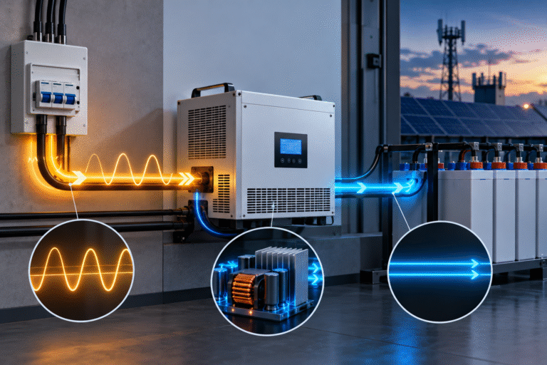
A battery charger is a power-conversion device.
It converts AC electricity from:
- Utility grid
- Generator
- UPS source
into controlled DC electricity for the battery.
The AC input must supply:
- Battery charging power
- Charger conversion losses
and the required AC current also depends on:
- Input voltage
- Power factor
- Single-phase or three-phase supply
These details matter when selecting:
- AC breakers
- Cables
- Generators
- Transformers
- Rectifier chargers
- Commercial ESS charging equipment
For larger LiFePO4 systems, charger AC-side design should not be based on DC output power alone.
Start with DC Charging Power
For a battery charger:
DC Charging Power ≈ Charging Voltage × Charging Current
Suppose a 51.2V-class battery is charging around: 56V
at: 100A
DC output power is approximately: 56 × 100 = 5.6kW
Notice that using: 51.2 × 100
would give: 5.12kW
but actual charging voltage is higher than nominal battery voltage.
For charger sizing, operating voltage matters.
Nominal Battery Voltage Is Not Charger Output Voltage
A battery described as: 51.2V 200Ah
has nominal energy: 51.2 × 200 = 10.24kWh
But during charging, charger voltage may be higher than 51.2V.
Therefore:
Charger kW should not always be calculated using nominal voltage.
Use the actual charging-voltage range specified by the battery manufacturer.
Charger Efficiency Comes Next
No charger is 100% efficient.
Part of the AC input becomes:
- semiconductor heat
- magnetic losses
- fan consumption
- control-system consumption
A simplified relationship is:
AC Real Power Input = DC Output Power ÷ Charger Efficiency
Suppose:
DC output = 5.6kW
Charger efficiency = 94%
Approximate AC real-power requirement: 5.6 ÷ 0.94 ≈ 5.96kW
The grid must therefore supply closer to 6kW than 5.6kW.
Efficiency Changes with Load
A charger may not maintain exactly the same efficiency at:
- 10% load
- 50% load
- 100% load
Power electronics often have an optimal operating range.
At very light load, fixed internal consumption becomes a larger percentage of total power.
At very high load, thermal and conduction losses can increase.
For detailed commercial design, use the manufacturer’s efficiency curve where available.
What Is Power Factor?
Power factor describes the relationship between: real power in kW and apparent power in kVA
A simplified relationship is: Power Factor = kW ÷ kVA
A charger with: PF = 1.0
uses the AC supply very efficiently from the perspective of current and apparent power.
A lower power factor requires more AC current to deliver the same real power.
Why Power Factor Matters
Consider two chargers delivering the same DC power.
Charger A
Power factor ≈ 0.99
Charger B
Power factor ≈ 0.70
Both may deliver approximately the same battery charging power.
But Charger B can draw significantly more RMS current from the AC supply.
This affects:
- cable sizing
- breaker sizing
- generator sizing
- transformer loading
For larger battery chargers, active PFC—Power Factor Correction—is therefore valuable.
Single-Phase AC Current Calculation
For a simplified single-phase calculation: Current ≈ Real Power ÷ (Voltage × Power Factor)
Suppose:
AC real power = 6kW
Input voltage = 230V
Power factor = 0.95
Current:
6000 ÷ (230 × 0.95) ≈ 27.5A
A simple calculation using: 6000 ÷ 230
would give only: 26.1A
Power factor changes the result.
Lower AC Voltage Means Higher Current
Suppose the same charger operates from: 120V AC instead of 230V.
For approximately 6kW of real input power and 0.95 PF: 6000 ÷ (120 × 0.95) ≈ 52.6A
The required current almost doubles.
This illustrates why higher AC voltage is commonly used for larger charging equipment.
AC Voltage Drop Can Reduce Charger Performance
Suppose a charger is designed for 230V.
When charging starts, site voltage falls to: 205V
because of:
- weak grid
- long AC cables
- overloaded generator
- undersized transformer
To maintain the same power, input current may increase.
Eventually the charger may:
- derate
- disconnect
- trigger AC undervoltage protection
A battery charging problem can therefore originate on the AC side.
Three-Phase Chargers Use a Different Calculation
For a balanced three-phase system, a common simplified formula is: P = √3 × V × I × PF
where V is line-to-line voltage.
Therefore: I = P ÷ (√3 × V × PF)
Suppose a charger requires approximately: 30kW AC real power
from a: 400V three-phase system
at: 0.95 PF
Current is approximately: 30,000 ÷ (1.732 × 400 × 0.95) ≈ 45.6A per phase
This is very different from supplying 30kW from single-phase AC.
Why Three-Phase Charging Is Useful for Commercial ESS
As charging power increases, single-phase current becomes impractical.
For example, charging:
- 50kWh
- 100kWh
- 200kWh
battery systems within a short period may require tens of kilowatts of charger power.
Three-phase supply can provide:
- lower current per conductor
- balanced loading
- practical commercial power distribution
This is why industrial rectifiers, UPS chargers and commercial ESS PCS equipment commonly use three-phase AC.
120/208V Three-Phase Systems Need Correct Interpretation
Some international projects use: 120/208V three-phase instead of 230/400V.
In a typical 120/208V system:
- line-to-neutral ≈ 120V
- line-to-line ≈ 208V
A three-phase charger designed for 400V AC cannot automatically operate on 208V.
Input-voltage compatibility must be confirmed.
This is especially relevant in projects in North America, Central America and other markets using 208/120V distribution.
Charger Nameplate Should Be Checked Carefully
A professional charger specification may include:
- AC input voltage
- Input-voltage range
- Frequency
- Phase
- Maximum input current
- Power factor
- Efficiency
- DC output voltage
- DC output current
All these values matter.
Do not request only: “125V 100A charger” without defining the AC side.
Example: 125V 100A DC Charger
Suppose an industrial battery system requires: 125V DC
at: 100A
Maximum DC output power is approximately: 125 × 100 = 12.5kW
If actual charging voltage rises above nominal system voltage, output power may be higher.
Allowing for charger efficiency, AC input could exceed 13kW.
Now the supplier needs to know whether AC input is:
- 220V single phase
- 380/400V three phase
- 208/120V three phase
- another system
The same DC charger specification can require very different AC input currents.
Generator Sizing Must Use AC Input Requirements
Suppose battery charging requires: 10kW DC
A customer selects a: 10kW generator
This provides essentially no margin for:
- charger losses
- power factor
- building loads
- transient loads
The generator may operate continuously near or above its comfortable output.
Instead, calculate the total AC-side requirement.
Include:
- charger real power
- apparent power
- simultaneous loads
- operating margin
kW and kVA Are Not the Same
Generators and transformers may be rated in: kVA
while loads are often discussed in: kW
Power factor links the two.
For example:
A 10kW load at PF 0.8 requires: 10 ÷ 0.8 = 12.5kVA
This is important when selecting generator or transformer capacity for battery charging.
Power Factor Correction Can Reduce Required kVA
A charger with active PFC may operate with a power factor close to unity.
This reduces apparent-power demand.
For large projects, improved PF can mean:
- smaller generator requirement
- lower conductor current
- lower transformer loading
- reduced utility penalties where applicable
Therefore, charger quality is not only about DC voltage stability.
AC-side performance matters too.
Harmonics Also Matter in Large Chargers
Power-electronic chargers do not necessarily draw perfectly sinusoidal current.
Poor-quality rectifiers can create harmonic current.
Large commercial installations may therefore need to consider:
- THD
- transformer heating
- generator compatibility
- power-quality requirements
For small residential chargers this may not be a major design concern.
For large rectifier systems, it can be important.
Frequency Compatibility
Charging equipment should also match local AC frequency.
Common systems use:
- 50Hz
- 60Hz
Many modern chargers support both.
But this should still be confirmed—especially for:
- industrial rectifiers
- UPS chargers
- project-specific equipment
Do not assume universal compatibility.
Charger Efficiency Affects Heat
If a charger outputs: 20kW
at: 94% efficiency
input power is approximately: 20 ÷ 0.94 ≈ 21.28kW
Difference: ≈ 1.28kW
A significant portion of this becomes heat.
The charger room therefore requires suitable:
- ventilation
- cooling
- spacing
At larger power levels, conversion losses become a thermal-design issue.
Why Charger Power Can Drop in Hot Rooms
Power electronics have temperature limits.
A charger operating in a hot electrical room may reduce output to protect:
- semiconductors
- magnetics
- internal capacitors
The customer may see:
“The charger is rated at 100A, but it only gives 70A.”
The cause may be AC charger thermal derating—not the battery.
Battery Limit and Charger Limit Are Separate
Suppose:
Charger maximum = 100A
Battery BMS maximum = 80A
Actual charge current must remain within the battery limit.
Now reverse the situation:
Charger maximum = 60A
Battery can accept = 100A
Actual current is limited by the charger.
Always determine the lowest limit in the system.
Parallel Batteries Change the Required DC Current
Suppose four: 51.2V 100Ah
batteries operate in parallel.
Total capacity: 400Ah
If the project wants 0.2C charging: 400 × 0.2 = 80A
At approximately 56V charging voltage, DC power is around: 56 × 80 = 4.48kW
This can then be converted into the required AC input power using charger efficiency and PF.
Example: 20kWh Battery, 4-Hour Charging Window
Suppose battery capacity: 20kWh
Energy to restore: 14kWh
Required charging window: 4 hours
Average stored-energy rate: 14 ÷ 4 = 3.5kW
Allowing for:
- charge taper
- conversion losses
- loads
the charger may need to be sized higher than 3.5kW.
After choosing DC charger power, calculate AC input current.
Do not stop the design at the battery side.
Why Breakers Trip When the Charger Is Upgraded
A customer replaces: 2kW charger
with: 5kW charger
Battery charging improves.
But now the AC breaker trips.
Possible cause:
The AC branch was sized for the old charger.
The new charger draws much more input current.
Battery-side upgrades often require AC-side upgrades too.
AC Cable Length Matters
Long AC runs create voltage drop.
A charger located far from the distribution board may experience lower voltage than the main panel.
At high charging power this can cause:
- increased current
- heating
- charger derating
- unstable charging
AC cable sizing should consider both:
- ampacity
- voltage drop
Three-Phase Phase Balance Matters
A true three-phase charger generally draws power from all phases.
If several single-phase chargers are used instead, distribute them carefully across phases.
Poor phase balance can create:
- one heavily loaded phase
- neutral-current issues
- voltage imbalance
Commercial projects should review the complete electrical distribution design.
Information to Send the Charger Manufacturer
For an industrial LiFePO4 charger, provide:
DC Side
- Battery nominal voltage
- Charging-voltage range
- Battery capacity
- Required charging current
- Maximum current
- BMS communication requirement
AC Side
- Input voltage
- Single-phase or three-phase
- Frequency
- Generator or grid supply
- Required power factor where specified
Communication
- Modbus RTU/TCP
- CAN
- RS485
- SCADA requirement
This produces a much more accurate quotation.
For Telecom and UPS Projects
Industrial backup systems may use:
- rectifier charger
- battery bank
- DC distribution
- SCADA monitoring
The charger is part of the complete DC power system.
Specification should include:
- normal charging
- float/standby requirements where applicable
- boost charging
- current limiting
- alarm contacts
- communication
LiFePO4 conversion may require different settings from a traditional lead-acid rectifier.
Troubleshooting Low Charging Power
If the charger output is lower than expected, check:
- AC input voltage
- AC current
- Input frequency
- Charger temperature
- Charger power limit
- Battery voltage
- BMS CCL
- Charger efficiency/derating
- Generator capacity
- Active AC loads
Do not automatically increase the battery current setting.
Common Calculation Mistakes
Avoid:
- Using nominal battery voltage instead of actual charging voltage
- Assuming AC input power equals DC output power
- Ignoring charger efficiency
- Ignoring power factor
- Confusing kW and kVA
- Using single-phase formulas for three-phase systems
- Ignoring simultaneous loads
- Ignoring voltage drop
These errors become increasingly expensive as charger power increases.
Conclusion
A LiFePO4 charger rated for several kilowatts is not simply a resistor that consumes the same number of kilowatts from the wall.
The AC side must account for:
- DC charging power
- charger efficiency
- power factor
- AC voltage
- number of phases
For small residential chargers, the difference may be manageable.
For large commercial, telecom and UPS charging systems, these calculations directly affect:
- breaker size
- cable size
- generator capacity
- transformer loading
- equipment cost
HIZN supplies LiFePO4 battery solutions for residential, commercial, telecom and industrial backup applications.
For charger-matching projects, send us the battery voltage, capacity, required charging current, AC input voltage and phase configuration. We can help define the battery-side charging requirements before charger selection.