
Introduction
A commercial customer requests a 100kWh LiFePO4 battery system. The battery supplier asks which PCS will be used, but the customer replies:
“Why do I need a PCS? Can’t I just use a battery charger?”
The answer depends on what the battery is expected to do.
A charger primarily moves energy toward the battery. A battery inverter moves energy from the battery toward AC loads. A bidirectional PCS, or Power Conversion System, can normally transfer energy in both directions between the battery and an AC electrical system.
For a simple DC backup installation, a charger may be all that is needed. For grid-connected peak shaving, solar energy shifting or commercial microgrids, bidirectional power conversion is usually central to the system architecture.
Understanding the difference helps B2B buyers specify a complete ESS instead of purchasing a battery first and trying to solve power conversion later.
What Does a Battery Charger Do?
A conventional AC battery charger converts:
AC → DC
Its primary function is to take power from a utility grid or generator and charge the battery according to specified voltage and current limits.
A charger may include communication, current limiting and intelligent charging logic, but the basic power direction is toward the battery.
This architecture is common in applications where the battery later supplies a DC load directly, such as certain telecom and industrial DC systems.
What Does an Inverter Do?
A conventional inverter converts:
DC → AC
It takes battery energy and supplies AC loads.
A standalone inverter may have no ability to recharge the battery. In that case, a separate charger is required.
Older off-grid systems often used separate devices for charging and inversion. Modern hybrid equipment increasingly combines these functions.
What Is a Bidirectional PCS?
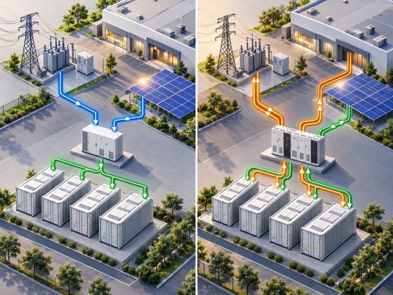
A bidirectional PCS can normally transfer power in both directions:
AC → DC for battery charging and DC → AC for battery discharging
This is fundamentally useful for commercial energy storage because the same equipment can charge the battery when energy is inexpensive or abundant and discharge it when energy is valuable.
A PCS also typically provides higher-level control functions associated with grid interaction, although exact capabilities vary by manufacturer and application.
Why Commercial ESS Needs Bidirectional Power Flow
Consider a factory installing a battery for peak shaving. During the night, the system may charge from the grid when tariffs are lower. During the afternoon, the battery discharges to reduce grid demand.
The required daily power flow is therefore: Grid AC → PCS → Battery
followed later by: Battery → PCS → Factory AC Bus
A charger alone can perform only the first half. Another inverter would still be needed for the second half.
A bidirectional PCS combines both directions into a coordinated power-conversion system.
Residential Hybrid Inverters Use the Same Basic Idea
A home hybrid inverter is effectively a smaller integrated bidirectional power-conversion device. It can coordinate solar, battery, grid and loads.
Commercial systems use similar principles at much larger power levels, with additional requirements for protection, communication, grid control and energy management.
This is why a 100kWh project should not simply scale up a small residential charger.
When a Standalone Charger Makes Sense
A standalone charger remains useful in many applications. Telecom systems, for example, may use rectifiers that supply a 48V DC load continuously while maintaining the battery. During a grid outage, the battery supplies the same DC bus directly.
Because the main load is DC, there may be no need to repeatedly convert battery power into AC.
Standalone chargers are also useful for emergency charging, workshop maintenance, warehouse battery servicing and certain UPS architectures.
Charger + Separate Inverter Is Another Option
A system can use one charger for AC-to-DC conversion and a separate inverter for DC-to-AC conversion. This can provide modularity and redundancy.
For example, an off-grid site might have a dedicated generator charger plus a separate solar inverter. If the inverter fails, battery charging capability may still remain.
However, separate equipment also requires careful coordination of voltage, current, communication and protection. More boxes do not automatically mean a better system.
Why One Bidirectional PCS Can Simplify Control
With one bidirectional PCS, the EMS can instruct a single power-conversion system to:
- Charge at 30kW
- Stop charging
- Discharge at 50kW
- Maintain zero export
- Support a demand limit
- Respond to grid conditions
This simplifies dispatch compared with independently coordinating a large charger and separate inverter.
For commercial projects, control integration can be as important as conversion efficiency.
kW Rating Is Different from Battery kWh
A common purchasing mistake is specifying only: 100kWh battery
without defining PCS power.
One 100kWh battery might be paired with a 20kW PCS for a five-hour-type application. Another might require a 100kW PCS for high-power peak shaving.
The battery capacity is the same, but the required power electronics are completely different.
Always specify both: Battery energy = kWh and PCS power = kW
Charging Power Must Match the Battery
Suppose a 100kWh battery is paired with a 100kW PCS. That does not automatically mean the battery should be charged at the full 100kW.
The battery’s permissible charging power depends on:
- Cell specification
- BMS limits
- Battery voltage
- Thermal design
- Number of racks
The PCS may have to operate below its nameplate power when the battery communicates a lower Charge Current Limit.
Battery and PCS should therefore be matched as one system.
Battery Voltage Is a Critical Interface
A PCS is designed for a defined DC operating range. For example, a high-voltage commercial PCS may expect several hundred volts from the battery.
A 51.2V residential battery cannot be connected simply because the PCS power rating looks suitable.
Before integration, compare:
- Minimum PCS DC voltage
- Nominal battery voltage
- Maximum battery charge voltage
- Maximum PCS DC voltage
- Current limits across the operating range
The complete voltage window must be compatible.
Why High-Voltage Batteries Are Common with Large PCS Equipment
Power equals voltage multiplied by current. Delivering 100kW from a 51.2V battery would require extremely high current.
At 500V, the same 100kW requires roughly one tenth of the current.
This is why larger commercial PCS systems are often paired with high-voltage battery racks rather than very large low-voltage parallel banks.
The design reduces DC current and makes cables, busbars and protection more practical.
Communication Is More Than SOC Display
In a commercial ESS, the battery BMS and PCS may exchange information such as:
- SOC
- SOH
- Pack voltage
- Maximum charge current
- Maximum discharge current
- Maximum charge voltage
- Temperature
- Fault status
- Contactor status
This allows the PCS to adjust power dynamically.
Without correct communication, the PCS may need to operate using conservative fixed limits.
EMS, PCS and BMS Have Different Roles
These three terms are often confused.
BMS — Battery Management System
Protects and manages the battery.
PCS — Power Conversion System
Moves electrical power between battery DC and the AC system.
EMS — Energy Management System
Decides when and why the battery should charge or discharge.
For example, the EMS may decide to discharge 50kW to reduce grid demand. The PCS performs the power conversion. The BMS confirms whether the battery can safely provide the requested power.
A commercial ESS requires these layers to cooperate.
Example: Peak Shaving
Suppose a factory normally peaks at 600kW, but the customer wants grid demand limited to 500kW.
When facility load rises to 570kW, the EMS can request: 70kW battery discharge
The PCS converts battery DC into AC and supplies the factory bus.
Later, when load falls and electricity is inexpensive, the EMS instructs the PCS to recharge the battery.
This application cannot be achieved with a simple one-direction charger alone.
Example: Solar Self-Consumption
A commercial building has 200kW of rooftop solar. At midday, PV production exceeds building load by 60kW.
The EMS commands the PCS to charge the battery at approximately the available surplus power. In the evening, solar disappears and building load remains high, so the PCS reverses direction and discharges.
Bidirectional conversion allows the battery to shift solar energy through time.
Example: Backup Power
A commercial ESS may also need to support loads during a grid failure. This requires more than charging capability.
The power-conversion equipment may need to establish or support an AC microgrid, depending on system architecture. Not every grid-following PCS can provide standalone backup operation.
When backup is required, confirm whether the system supports:
- Grid-forming operation
- Black start
- Seamless transfer
- Backup output
- Generator integration
Do not assume every bidirectional PCS automatically functions as a UPS.
Grid-Tied and Off-Grid PCS Are Not Identical
Some PCS products are optimized primarily for grid-connected charging and discharging. Others can operate in isolated microgrids.
The difference matters if the customer expects the battery to power the site when utility AC completely disappears.
Ask the PCS supplier whether off-grid operation is supported and what additional equipment is required.
Why “Bidirectional” Does Not Automatically Mean “Hybrid Solar”
A PCS can be bidirectional without containing solar MPPT inputs.
In a commercial AC-coupled system, solar may use separate PV inverters while the PCS connects the battery to the AC bus.
The energy flow might be: PV → PV Inverter → AC Bus → PCS → Battery
This is different from a residential hybrid inverter that contains PV MPPTs and battery conversion inside one device.
Architecture should be confirmed before purchasing equipment.
Standalone Chargers Can Provide Useful Redundancy
Even a PCS-based ESS may include an auxiliary charger in certain critical applications. For example, a maintenance charger or independent emergency charging source can provide limited battery recovery if the primary PCS is unavailable.
Whether this is economically justified depends on system criticality. It is more common in specialized industrial, telecom or emergency-power designs than in ordinary residential ESS.
Redundancy should be designed deliberately rather than created by randomly connecting multiple chargers.
Efficiency Should Be Evaluated Across the Required Power Range
Commercial buyers often compare PCS peak efficiency. However, a system may operate much of the day at only 20–40% of rated power.
Efficiency at partial load can therefore matter. Auxiliary consumption from cooling, control electronics and transformers should also be included when estimating round-trip performance.
A highly efficient battery cannot compensate for poorly matched power electronics.
Transformer-Based and Transformerless Architectures
Some PCS systems include or require transformers for voltage conversion, isolation or grid interface. Others use transformerless architectures.
Each approach has implications for:
- Efficiency
- Size
- Grounding
- Isolation
- Grid voltage
- Cost
This should be decided at the overall electrical-design level rather than from battery voltage alone.
Three-Phase Commercial Systems
Large ESS projects typically interface with three-phase AC systems. The PCS may be designed for voltages such as 400V or other regional standards.
Before quotation, confirm the site’s actual:
- Line-to-line voltage
- Frequency
- Grid type
- Transformer arrangement
A PCS designed for one AC system cannot automatically be deployed on another.
How to Select the PCS Power Rating
Start from the application rather than battery capacity alone. Ask how quickly the battery must charge, how much peak power it must discharge, whether the system performs peak shaving and whether emergency backup requires supporting a particular load.
For example, a 50kWh battery used only to supply 10kW overnight has very different PCS requirements from a 50kWh battery expected to support a 40kW commercial load.
The correct PCS rating follows the real power profile.
A Useful Procurement Table
| Project Question | Why It Matters |
|---|---|
| Required battery capacity (kWh) | Determines energy storage |
| Maximum charge power (kW) | Determines recharge rate |
| Maximum discharge power (kW) | Determines load support |
| Battery DC voltage range | Must match PCS |
| AC voltage and phase | Defines grid interface |
| Grid-connected only or backup | Determines PCS operating mode |
| PV capacity | Influences charging architecture |
| Generator integration | Affects control and power flow |
| CAN/RS485 protocol | Required for BMS integration |
| EMS requirement | Determines dispatch strategy |
Providing these parameters produces a much more accurate ESS quotation than requesting only “100kWh lithium battery.”
Common Procurement Mistakes
One common mistake is buying the battery first and choosing the PCS later. Another is matching only nominal voltage without checking minimum and maximum DC ranges. Some projects also assume that a 100kW PCS should always charge a 100kWh battery at 100kW, ignoring battery current limits.
Commercial ESS should be treated as one coordinated electrical system. Battery, PCS and EMS interfaces should be confirmed before production.
Charger, Hybrid Inverter or PCS?
A simple way to think about the choices is:
| Equipment | Main Function | Typical Application |
|---|---|---|
| Standalone Charger | AC → DC | Maintenance, telecom, DC backup |
| Inverter | DC → AC | Standalone AC load supply |
| Hybrid Inverter | PV/Grid/Battery integration | Residential and small C&I |
| Bidirectional PCS | AC ↔ DC | Commercial and industrial ESS |
Actual product functions vary, but this framework helps identify the correct product category.
Conclusion
A standalone LiFePO4 charger and a bidirectional PCS solve different problems. If the project only needs to recharge a battery that supplies a DC bus, a charger may be sufficient. If the battery must repeatedly charge from and discharge back into an AC electrical system, bidirectional power conversion becomes essential.
For commercial ESS, the correct architecture should be chosen from the required kWh, kW, grid connection, backup function and operating strategy, not battery capacity alone.
HIZN supplies LiFePO4 battery solutions for residential, telecom, commercial and larger energy storage applications and can provide battery-side voltage, current and communication information for inverter or PCS integration.
For commercial energy storage projects, send us the required battery capacity, maximum charge/discharge power, AC grid voltage and PCS model. We can help confirm whether the proposed battery voltage, BMS current and communication architecture are suitable for the system.