
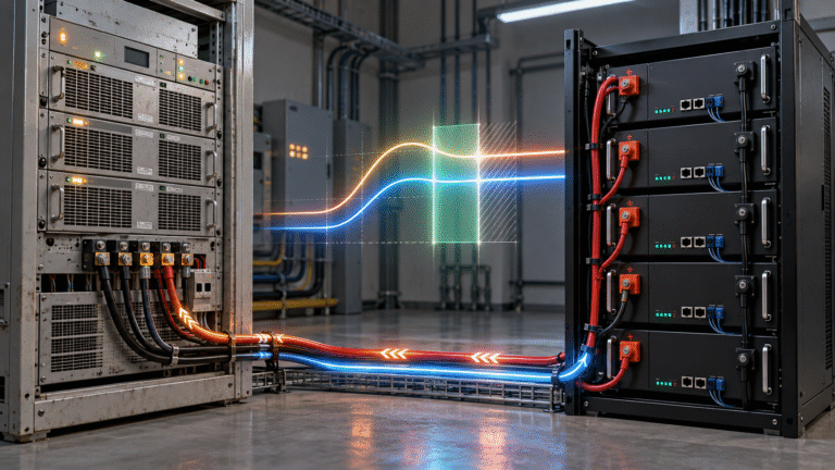
“48V” Is a System Class, Not One Exact Voltage
A traditional telecom battery system described as 48V does not operate at exactly 48.0V all the time. Lead-acid batteries may be charged at voltages significantly above nominal voltage and discharged below nominal voltage.
Similarly, a 51.2V LiFePO4 battery uses 51.2V as its nominal value, not its fixed terminal voltage.
Therefore, a 48V telecom rectifier and a 51.2V LiFePO4 battery can occupy overlapping electrical ranges. The real compatibility question is whether the rectifier’s adjustable output range matches the battery’s approved charging range while also remaining acceptable to the connected telecom loads.
Check the Rectifier Output-Voltage Range First
The most important rectifier specification is not simply “48V output.” Find the actual adjustable DC range.
A professional telecom rectifier may allow its output to be configured across a relatively broad range. If that range includes the battery manufacturer’s recommended charging settings, lithium operation may be possible.
If the rectifier has a fixed output or cannot reach the required voltage, the battery may remain chronically undercharged. If it applies excessive voltage, the BMS may repeatedly enter high-voltage protection.
The exact charging value should come from the specific LiFePO4 battery manufacturer rather than a generic internet setting.
The Telecom Load Must Accept the Same DC Bus
The rectifier does not charge the battery in isolation. The battery and telecom equipment are typically connected to a common DC bus.
If the rectifier voltage is changed to suit the new battery, the connected BTS, radio, transmission or other DC equipment must also tolerate that voltage.
This is a critical system-level point. A charging setting that is ideal for the battery is not acceptable if it exceeds the input-voltage limit of the telecom load.
Before conversion, review the allowable DC operating range of both sides.
Lead-Acid Float Settings May Not Be Ideal for LiFePO4
Traditional telecom rectifiers often maintain VRLA batteries on continuous float charge. That strategy is designed around lead-acid standby service.
LiFePO4 does not require the same traditional float behavior. Depending on the battery design, the rectifier may need a different standby or charging-voltage strategy.
If the rectifier provides configurable float and boost settings, these should be reviewed specifically for lithium operation. Do not simply keep the old VRLA values because the site has operated with them for years.
Equalization or Boost Functions Require Care
Some rectifier systems periodically apply a higher boost or equalization voltage to lead-acid batteries. These functions can be useful for certain lead-acid applications but are not automatically suitable for LiFePO4.
If the rectifier automatically raises voltage on a schedule, the lithium BMS may disconnect charging when a cell reaches its upper limit. The customer may then see repeated battery alarms that did not exist with the original lead-acid bank.
Any automatic equalization behavior should be identified and configured according to the lithium battery supplier’s recommendations.
Rectifier Current Is the Second Major Compatibility Check
Suppose the rectifier output voltage is compatible. The next question is how much current remains available for battery charging after telecom loads are supplied.
A site may have 150A of rectifier capacity, but if the active telecom load consumes 100A, only around 50A remains for battery charging in this simplified example.
Replacing a lead-acid battery with a larger lithium bank does not create additional rectifier capacity. If the battery energy increases significantly, recharge time may become much longer unless the rectifier system is also expanded.
Example: 51.2V 200Ah Telecom Battery
Consider a 51.2V 200Ah LiFePO4 battery. If the site load is 60A and the rectifier can provide 100A, approximately 40A may remain for battery charging.
If the battery needs 120Ah restored after an outage, an idealized calculation gives:
120Ah ÷ 40A = 3 hours
Actual recovery will be somewhat longer because charging current can change and the system has losses.
If the telecom load increases to 90A, only around 10A remains for charging and battery recovery becomes dramatically slower.
Recharge Time Is Often the Hidden Problem
A lithium retrofit may initially appear successful because backup runtime improves. The site survives a long outage, and the operator is satisfied.
The problem appears later when utility power returns. Because the new battery bank stores more energy, the existing rectifier may require many hours to restore it.
In a region with repeated outages, the battery can begin the next blackout at only 50% or 60% SOC. The operator may incorrectly conclude that lithium capacity has deteriorated when the real issue is inadequate recharge time.
Battery retrofit projects should therefore evaluate both backup runtime and post-outage recovery.
BMS Maximum Current Is Not the Target Rectifier Current
A 200A BMS does not mean the rectifier should be configured to charge at 200A. The BMS rating is one equipment limit, while the recommended routine charging current may be lower.
The correct charging current should consider battery capacity, cell specification, ambient temperature, required recovery time and rectifier capability.
Telecom sites normally benefit from a controlled, predictable recharge strategy rather than simply using the highest current the BMS can tolerate.
Can the Rectifier Communicate with the BMS?
Legacy telecom rectifiers were often designed around voltage-controlled lead-acid batteries and may have no direct CAN or RS485 interface to a lithium BMS.
That does not automatically prevent lithium use. An open-loop system can sometimes operate using correctly configured voltage and current limits while the BMS provides final protection.
However, the rectifier will not receive dynamic information such as Charge Current Limit or battery temperature unless an additional controller or compatible communication interface is used.
This means fixed settings need enough margin to avoid relying on BMS protection during normal operation.
Closed-Loop Integration Provides More Control
A modern telecom power controller can potentially use BMS data to monitor SOC, voltage, temperature, alarms and permissible current. This allows the charging system to respond more intelligently when battery conditions change.
For example, if the battery becomes hot, the BMS may request reduced charging current. A legacy open-loop rectifier would continue using its fixed current setting until protection occurs, while a communicating controller can reduce power earlier.
For large network deployments, remote BMS information also improves maintenance and fault diagnosis.
Negative-48V Telecom Architecture Needs Special Attention
Some telecom DC systems use a negative-48V architecture in which polarity and grounding conventions differ from ordinary residential solar systems. A lithium battery retrofit must respect the existing site architecture.
The battery manufacturer and telecom integrator should confirm terminal polarity, chassis bonding, communication isolation and any intentional DC grounding arrangement.
Do not assume that a rack battery designed for a residential inverter can be inserted into every telecom DC bus without interface review.
Low-Voltage Disconnect Logic May Need Adjustment
Lead-acid telecom systems can use voltage thresholds to trigger low-voltage disconnects. LiFePO4 has a flatter discharge-voltage curve and its BMS may also provide its own low-voltage protection.
Existing low-voltage disconnect settings should therefore be reviewed during conversion. A threshold designed around VRLA behavior may disconnect a lithium battery earlier or later than intended.
Although this parameter concerns discharge rather than charging, it directly affects how deeply the battery is depleted and how much energy the rectifier must restore afterward.
Battery SOC Monitoring Becomes More Valuable
Lead-acid telecom systems traditionally relied heavily on voltage and sometimes conductance measurements. LiFePO4 BMS systems can provide direct digital SOC estimates and cell-level information.
For repeated-outage sites, monitoring SOC is especially useful because voltage alone provides limited information through much of the LiFePO4 operating range.
A network-management system can use SOC trends to identify sites that are not recovering fully between outages.
Rectifier Redundancy Should Be Rechecked
A site may have N+1 rectifier redundancy based on the original telecom load and lead-acid charging assumptions. After a lithium retrofit, the desired battery recharge current may be higher.
If one rectifier fails, the remaining modules may still support the BTS load but provide almost no spare capacity for battery charging.
The site remains online, yet backup reserve recovers slowly. The operator should decide whether N+1 means “load survival only” or “load plus required battery recovery.”
High Ambient Temperature Can Reduce Rectifier Capacity
Telecom cabinets in hot regions can operate well above normal indoor temperatures. Rectifier modules may reduce output at elevated temperature.
This means a system theoretically capable of 150A may provide less during the hottest part of the day. If the battery also reduces charging current because of temperature, total recovery can become much slower than the nameplate calculations suggest.
For outdoor telecom sites, use real temperature-derated capacities when checking retrofit performance.
Solar-Hybrid Sites Add Another Layer
A telecom site may combine utility rectifiers with solar MPPT charging. The LiFePO4 battery can therefore receive charging current from both sources.
If the rectifier contributes 40A and the solar controller contributes 60A, the BMS can see approximately 100A total. Each source may appear safe individually while the combined current approaches the battery limit.
Hybrid-site commissioning should confirm total battery current under the highest expected solar and grid conditions.
What If the Rectifier Voltage Is Too Low?
If the rectifier’s highest practical setting remains below the battery’s required upper charging range, several symptoms can appear. The battery may operate normally at moderate SOC but never reach its intended full-charge condition. Cell balancing may have limited opportunity to operate, and BMS SOC calibration may gradually drift.
Increasing voltage beyond the rectifier’s certified range is not the answer. The correct solution may be a different rectifier or a battery specifically designed for the existing DC bus.
What If the Rectifier Voltage Is Too High?
An excessive charging target can push one or more cells toward high-voltage protection. The BMS may repeatedly stop charging while the rectifier continues attempting to maintain the same bus voltage.
This can create charge-stop-reconnect behavior and repeated alarms. Lowering BMS protection thresholds or bypassing the BMS is not an acceptable solution. The normal rectifier operating voltage must be compatible with the battery.
A Practical Retrofit Evaluation
Before converting a legacy site, compare five voltage/current interfaces: rectifier output range, telecom load input range, battery recommended charging range, battery BMS current capability and site protection-device ratings.
Then calculate battery recovery under real site load. A retrofit that is electrically compatible but takes twelve hours to recover during a location that only receives four hours of reliable grid power is still a poor design.
The project should be evaluated as a complete DC power system.
Information to Collect Before Quotation
For an existing telecom site, the most useful technical information includes rectifier manufacturer and model, adjustable output-voltage range, module current rating and quantity, normal/peak telecom load, original battery type, required backup time, DC grounding architecture and desired lithium battery capacity.
With these parameters, a battery supplier can determine whether the existing rectifier is likely to be reusable or whether changes should be planned.
Conclusion
A legacy 48V telecom rectifier can sometimes be used successfully with a 51.2V LiFePO4 battery, but compatibility should never be assumed from nominal voltage labels alone.
The retrofit must coordinate rectifier output voltage, telecom load voltage range, battery charging requirements, available charging current, BMS protection and required recovery time. Existing lead-acid float, boost and equalization settings should also be reviewed rather than copied directly.
HIZN supplies 48V/51.2V LiFePO4 battery solutions for telecom base stations, communication backup and solar-hybrid sites.
For a telecom lead-acid-to-lithium retrofit, send us the existing rectifier model, DC voltage settings, site load, battery quantity and required backup time. We can help evaluate whether the existing charging system can be retained or needs adjustment.