
Introduction
One of the most common questions asked by solar installers, distributors and energy storage buyers is:
How many LiFePO4 batteries can I connect in parallel?
Some battery suppliers advertise support for 8, 16 or even 32 parallel modules. However, the number printed on a battery datasheet is only one part of the answer.
The practical limit of a parallel LiFePO4 battery bank depends on the complete system, including:
- Battery BMS architecture
- Communication address capacity
- Inverter charging and discharging current
- Branch cable design
- DC busbar capacity
- Main breaker and fuse ratings
- Available installation space
- Fault-current level
- Battery age and condition
- Manufacturer approval
A system may be technically able to communicate with 32 battery modules while the inverter, busbar or main DC cables can safely support far fewer.
This guide explains how to determine a realistic parallel battery quantity for residential, commercial, telecom and off-grid energy storage systems.
What Changes When Batteries Are Connected in Parallel?
When identical batteries are connected in parallel:
- Nominal voltage remains unchanged.
- Amp-hour capacity increases.
- Total stored energy increases.
- Available discharge current may increase.
- Available charging current may increase.
- Fault current can increase significantly.
For example, four 51.2V 100Ah batteries connected in parallel produce:
- Nominal voltage: 51.2V
- Total capacity: 400Ah
- Nominal energy: 20.48kWh
Eight identical batteries produce:
- Nominal voltage: 51.2V
- Total capacity: 800Ah
- Nominal energy: 40.96kWh
Although the energy calculation is simple, the installation requirements become more demanding as additional batteries are added.
There Is No Universal Maximum Parallel Quantity
The maximum parallel quantity cannot be determined from battery voltage and capacity alone.
A 51.2V 100Ah battery from one manufacturer may support only four parallel units, while another model may support sixteen or more. The difference may be caused by:
- BMS communication design
- Master-slave architecture
- Firmware
- Internal contactor or MOSFET design
- Maximum communication addresses
- Approved branch protection
- Manufacturer testing
- Cable and busbar recommendations
Always use the maximum quantity specified for the exact battery model.
Do not assume that two batteries with similar voltage and capacity have the same parallel capability.
Limit 1: BMS Communication Capacity
Modern rack-mounted LiFePO4 batteries commonly use CAN or RS485 communication.
In a multi-battery system, the batteries may need to:
- Communicate with one another.
- Identify one battery as the master.
- Assign unique addresses to slave batteries.
- Combine current and capacity information.
- Send system limits to the inverter.
The communication design may have a fixed maximum number of battery addresses.
For example, a battery could use DIP switches that permit addresses from 1 to 16. In that case, the communication architecture may support a maximum of 16 modules unless an additional battery control unit is used.
A larger installation may require:
- A master BMS
- A battery cluster controller
- Multiple battery cabinets
- Separate communication loops
- A higher-level energy management system
Multiple parallel batteries can operate as one bank only when their BMS units and system controller are designed to coordinate their operating data and limits.
Limit 2: Inverter Battery Compatibility
Even when the battery supports many parallel modules, the inverter may not recognise them correctly.
Check whether the inverter can receive:
- Total battery capacity
- State of charge
- Charge current limit
- Discharge current limit
- Battery voltage
- Battery temperature
- Alarm information
- Number of connected modules
Some inverters communicate only with one master battery. The master battery must therefore calculate and transmit the limits for the complete bank.
Possible compatibility problems include:
- Incorrect SOC display
- Only one battery being recognised
- Charge current remaining too low
- Wrong battery capacity displayed
- Repeated communication alarms
- Battery current limit not increasing after expansion
- Inverter using an incompatible CAN protocol
Before selecting the battery quantity, confirm the exact battery-to-inverter communication protocol.
Limit 3: Maximum Combined Charging Current
Adding more batteries increases the battery bank’s theoretical charging capability, but it does not automatically increase the charging power available from the system.
The total charging current may come from several sources:
- Solar inverter
- MPPT charge controller
- Grid charger
- Generator charger
- Separate AC charger
- DC charging equipment
The combined maximum charging current must remain within:
- Battery bank charging limit
- BMS charge current limit
- Main cable rating
- Busbar rating
- Fuse rating
- DC breaker rating
For example, suppose each 51.2V 100Ah battery allows a recommended charging current of 50A.
With four batteries, the theoretical combined recommended limit could be 200A. However, if the busbar, main cable or inverter is rated for only 120A, the system should not be configured to charge at 200A.
The lowest safe system limit must be respected.
Limit 4: Maximum Combined Discharge Current
Parallel batteries can share the inverter load, but the inverter determines how much current the bank may need to deliver.
Approximate DC current can be estimated using:
DC Current = Inverter Power ÷ Battery Voltage ÷ Inverter Efficiency
A 5kW inverter operating from a 51.2V battery bank may draw approximately 100–110A at full power, depending on efficiency and battery voltage.
A 10kW inverter may require approximately 200–220A.
A 20kW system may exceed 400A.
As system power increases, installers must evaluate:
- Battery branch current
- Main cable size
- Number of parallel cables
- Busbar capacity
- Main breaker rating
- Short-duration surge current
- Voltage drop
- Terminal temperature
Installing more batteries does not correct an undersized DC distribution system.
Limit 5: Busbar and DC Combiner Capacity
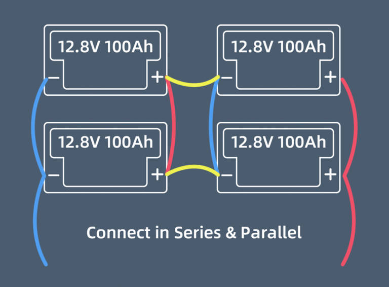
Small battery banks may use a simple diagonal connection. Larger systems should normally use positive and negative DC busbars or a battery combiner cabinet.
The busbars must be rated for the maximum expected current of the complete system.
A professional parallel battery arrangement should provide:
- One protected positive branch for each battery
- One negative branch for each battery
- Equal-resistance branch cables
- A correctly rated positive busbar
- A correctly rated negative busbar
- A main fuse or breaker
- A main disconnecting device
- Clearly labelled battery branches
If the battery bank grows from four modules to twelve modules, the original busbar may no longer be suitable even when there are unused connection points.
The number of available bolts is not the same as the rated current capacity.
Limit 6: Branch Fuse and Breaker Coordination
Every parallel battery can contribute current to a fault on another branch.
As more batteries are added, the possible fault current available at the common DC bus increases.
Each battery branch should therefore have correctly selected protection located close to the battery connection.
The design should consider:
- Battery short-circuit capability
- BMS interruption method
- Branch cable ampacity
- Fuse interrupting rating
- DC breaker breaking capacity
- Main protection coordination
- Busbar short-circuit withstand rating
A breaker rated for the normal operating current may still be unsuitable if its DC breaking capacity is lower than the available fault current.
Limit 7: Cable Length and Current Sharing
A parallel battery bank performs best when every battery has a similar electrical path to the common busbars.
Each branch should use:
- The same conductor material
- The same cable cross-sectional area
- The same positive cable length
- The same negative cable length
- The same fuse or breaker type
- The same lug type
- The same crimping method
- The same terminal torque
When ten or more batteries are installed, cable routing becomes more difficult. Batteries located farther from the busbars may require longer cables, increasing branch resistance.
This is one reason why large systems are often divided into cabinets or clusters instead of placing every battery on one long parallel bus.
Limit 8: Physical Rack and Cabinet Design
Parallel capacity is also limited by the installation structure.
Check:
- Rack loading capacity
- Floor loading
- Cabinet ventilation
- Cable entry space
- Maintenance access
- Emergency isolation
- Distance to the inverter
- Fire separation requirements
- Environmental protection
- Local electrical regulations
A 51.2V 100Ah rack battery may weigh approximately 40–50kg depending on its design. Sixteen modules could therefore exceed 700kg before including the rack, cables, busbars and protection devices.
The floor and rack must be evaluated before installation.
Limit 9: Battery Temperature
Batteries installed in parallel should operate in a similar thermal environment.
Avoid installing some batteries:
- Directly beside a hot inverter
- In direct sunlight
- Near an air-conditioning outlet
- At the top of a poorly ventilated cabinet
- In a separate room with a different temperature
- Against an uninsulated hot wall
Temperature differences affect internal resistance, charging behaviour and available capacity.
A battery operating at a higher temperature may share current differently and age faster than the other modules.
Limit 10: Battery Age and State of Health
The maximum number of new identical batteries is not necessarily the maximum number that should be added to an old system.
An existing battery bank may have:
- Reduced capacity
- Increased internal resistance
- Different firmware
- Different cell supplier
- Different cycle count
- Different SOC calibration
- Different charging history
Adding many new batteries to a heavily aged bank may create poor current sharing and inconsistent SOC behaviour.
Before expanding an old system, compare:
- Battery age
- Remaining capacity
- Internal resistance
- Cycle count
- Cell voltage consistency
- BMS firmware
- Alarm history
In some cases, replacing the old bank is more reliable than adding new modules.
Practical Parallel Quantity Examples
Example 1: 5kW Home Energy Storage System
Battery:
- 51.2V 100Ah
- 5.12kWh per module
- 100A continuous discharge BMS
Possible battery quantity:
- Two modules for approximately 10.24kWh
- Three modules for approximately 15.36kWh
- Four modules for approximately 20.48kWh
The quantity is normally determined by required backup time rather than inverter current, because even two modules may already provide sufficient current for a 5kW inverter.
Example 2: 12kW Off-Grid System
Battery:
- 51.2V 100Ah
- 100A continuous discharge per module
The inverter may require more than 230A at full output.
At least three battery modules may be needed for discharge-current capability, but additional modules may be required for:
- Backup duration
- Reduced current per battery
- Longer cycle life
- Generator-free operation
- Future load growth
Four to eight modules may provide a more practical design depending on the load profile.
Example 3: 50kWh Commercial System
Using 51.2V 100Ah modules:
- Ten modules provide 51.2kWh nominal energy.
At this scale, the system should usually include:
- A battery cabinet or professional rack
- DC busbars
- Individual branch protection
- Main DC protection
- Master-slave BMS communication
- Emergency isolation
- Monitoring
- Documented commissioning
The system should not be treated as ten independent household batteries connected with improvised cables.
How to Determine the Correct Maximum Quantity
Use the following sequence.
Step 1: Confirm Battery Approval
Ask the battery supplier:
- What is the maximum parallel quantity?
- Is an external master BMS required?
- What firmware is required?
- Which inverter protocols are supported?
- Can multiple cabinets be connected?
Step 2: Calculate Required Energy
Determine:
- Daily energy consumption
- Required backup duration
- Maximum depth of discharge
- System losses
- Future expansion allowance
Step 3: Calculate Required Power
Check:
- Inverter continuous power
- Inverter surge power
- Maximum DC discharge current
- Maximum charging current
- Generator charging current
Step 4: Design the DC Distribution
Select:
- Branch cable size
- Branch fuse or breaker
- Busbar rating
- Main cable size
- Main fuse
- Main disconnect
- Pre-charge system
Step 5: Verify Communication
Confirm:
- Master battery address
- Slave address range
- CAN or RS485 wiring
- Termination requirements
- Inverter protocol
- Total capacity reporting
Step 6: Review Installation Conditions
Evaluate:
- Rack capacity
- Floor loading
- Ventilation
- Temperature
- Maintenance clearance
- Local safety requirements
Common Mistakes
Assuming More Batteries Always Improve Performance
More batteries increase capacity, but they also increase cost, fault current, wiring complexity and communication requirements.
Using the Advertised Maximum Without Engineering Review
“Supports 32 batteries” does not mean that every inverter, busbar and installation can use 32 batteries safely.
Connecting All Batteries to One Terminal
Stacking many lugs on one battery terminal creates poor current sharing and mechanical stress.
Ignoring Main Cable Capacity
Branch cables may be correctly sized while the main cable remains too small for the combined current.
Mixing Different Battery Models
Different BMS behaviour and internal resistance can cause repeated alarms and uneven loading.
Frequently Asked Questions
Can I connect 16 LiFePO4 batteries in parallel?
Only when the exact battery model, BMS, inverter, busbar and protection system are approved for 16 modules.
Does connecting more batteries increase voltage?
No. In a parallel connection, nominal voltage remains unchanged.
Does parallel connection increase maximum current?
The battery bank’s theoretical current capability normally increases, but the usable system current remains limited by the inverter, BMS, cables, busbars and protection devices.
Can I connect batteries without communication?
Some systems can operate in voltage-control mode, but closed-loop CAN or RS485 communication is generally preferred for modern energy storage systems.
Is there a recommended maximum for residential systems?
There is no universal number. Many residential projects use two to eight 48V or 51.2V modules, while larger systems may require a commercial battery cabinet architecture.
Conclusion
The maximum number of parallel LiFePO4 batteries is determined by much more than the battery datasheet.
A complete assessment must include:
- BMS communication capacity
- Battery model approval
- Inverter compatibility
- Charging and discharge current
- Branch protection
- Main protection
- Cable and busbar capacity
- Fault-current level
- Rack and floor loading
- Battery age and condition
For a reliable system design, provide HIZN Lithium with:
- Inverter brand and model
- Inverter power
- System voltage
- Required backup time
- Maximum load
- Solar array power
- Generator or grid charging current
- Planned battery quantity
- Future expansion requirements
This information allows the battery capacity, BMS current, communication architecture and DC distribution system to be evaluated together.