
Introduction
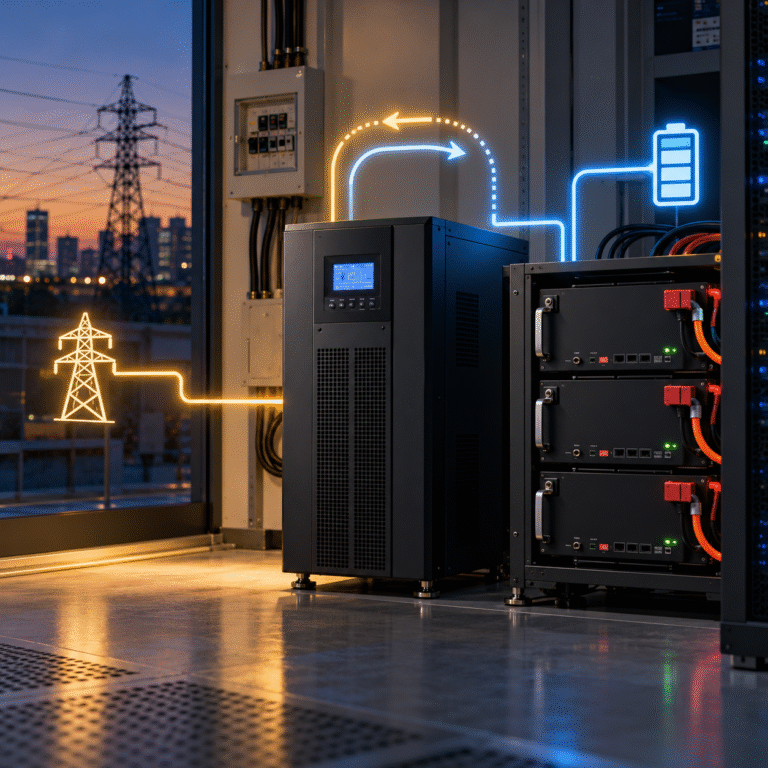
Utility power returns after an outage. The customer expects the UPS to transfer back to mains power and begin recharging the LiFePO4 battery. Instead, the UPS behaves strangely. It returns to mains for several seconds, then switches back to battery. A short time later it tries mains again, then returns to battery again.
The customer sees the battery discharging and charging repeatedly and assumes the new LiFePO4 battery is incompatible with the UPS. Sometimes battery integration can contribute to the behavior, but in many cases the real problem is on the AC input side.
When the UPS transfers back to grid, its battery charger can immediately add substantial electrical load. If the restored utility source, generator, extension cable or upstream wiring is weak, AC voltage or frequency can move outside the UPS acceptance window. The UPS rejects mains power and returns to battery.
Once the charger load disappears, the AC source recovers. The UPS sees acceptable power again and reconnects. The result is a repeating cycle. For UPS distributors and battery dealers, this is a valuable troubleshooting topic because the battery is often blamed even when the battery is functioning correctly.
The UPS Does Not Accept Every Available AC Source
A UPS monitors incoming AC power continuously. Depending on model, it can evaluate voltage, frequency and sometimes other power-quality conditions. If incoming power falls outside the accepted operating window, the UPS transfers to battery to protect the load.
When grid power returns, the UPS usually does not reconnect blindly. It waits until the source meets its required conditions. This process is often described as input qualification or retransfer. The exact thresholds and delay vary by UPS model.
Why the Problem Often Appears Only After an Outage
Before the outage, the battery may have been nearly full. The UPS charger therefore required little charging power. After a long outage, the battery may be at 20–40% SOC and capable of accepting substantial current.
When grid power returns, the UPS suddenly has two jobs: support the connected AC load and recharge the depleted battery. The total input demand can therefore be much higher than before the outage. A grid connection that looked stable before the blackout may sag once the charger starts.
A Typical Transfer-Cycling Sequence
Consider the following sequence. The grid returns at acceptable voltage. The UPS waits for its reconnection delay, then transfers from battery to mains. Immediately afterward, the charger starts supplying high current to the LiFePO4 battery.
AC input current rises. Because the local grid or supply cable is weak, UPS input voltage drops below its accepted range. The UPS disconnects from mains and returns to battery. Once the charger stops, grid voltage rises again. The UPS waits, reconnects, starts charging and repeats the same event. From the customer’s perspective, it looks like the battery is forcing the UPS to switch modes. The real trigger is AC voltage instability under charging load.
LiFePO4 Can Make the Problem More Visible
A lithium battery can often accept higher charging power than the lead-acid battery bank it replaced. Suppose the old VRLA system charged slowly at a modest current. After upgrading to LiFePO4, the installer increases charger current to take advantage of faster lithium recovery.
The UPS now draws more AC input power after an outage. If the upstream electrical system was already marginal, the larger recharge demand can expose the weakness. The LiFePO4 battery is not necessarily defective. Its faster charging capability has changed the site load profile.
Example: Weak Utility Connection
Imagine a UPS supporting 2kW of critical load. After an outage, the charger begins adding another 3kW of input demand. The utility connection now needs to supply more than 5kW after accounting for UPS losses. If the UPS is connected through a long or undersized AC cable, voltage can sag significantly.
The UPS sees undervoltage and switches back to battery. Reducing charging current may make the cycling disappear immediately. This strongly indicates an AC-side capacity problem.
Generator Sites Are Even More Sensitive
Remote UPS systems are frequently powered by generators during extended grid failures. A generator may show correct voltage and frequency before the UPS connects. The customer assumes it has enough capacity. Once the UPS transfers and the charger starts, generator load increases sharply.
Engine speed drops, frequency falls and voltage may sag. The UPS rejects the generator and goes back to battery. The generator then recovers because the large charging load disappeared. The cycle repeats. This is a classic generator-charger interaction problem.
Generator kVA Should Include Battery Recharge
Customers often size a generator for the critical AC load only. For example, the site load is 5kW, so they install a generator slightly above that value. However, after an outage, the UPS may also want several kilowatts for battery charging.
The generator therefore needs enough capacity for: critical load + battery charger + UPS losses + operating margin. If recharge power is not included, transfer instability can occur even though the generator comfortably supports the load when the charger is disabled.
AC Frequency Can Trigger the Same Behavior
Voltage may look normal while generator frequency is unstable. Suppose the UPS accepts a defined frequency window. When battery charging begins, generator engine speed decreases and frequency falls outside that window. The UPS returns to battery.
Once charger load disappears, frequency returns to normal and the UPS reconnects. A technician looking only at AC voltage can miss this completely. Record both voltage and frequency during the transfer event.
UPS Input Modes Can Have Different Acceptance Windows
Some UPS equipment provides operating modes such as: UPS / Sensitive Load Mode and Generator / Appliance Mode
The names vary by manufacturer. A strict mode may accept only a narrow AC voltage and frequency range. A wider mode may tolerate more variation. This can influence transfer cycling on weak grids or generators.
However, changing the acceptance range should follow the UPS manufacturer’s guidance and consider the connected loads. Do not widen protection limits blindly simply to stop switching.
Recharge Current Is One of the First Settings to Check
If transfer cycling appears only after a deep battery discharge, reduce the charger current temporarily as a diagnostic test. For example, if the UPS is configured to charge at 100A, test at a significantly lower approved current.
If AC input becomes stable and the UPS remains on mains, the problem is likely related to available AC power or upstream voltage drop. This does not necessarily mean the customer must permanently use the lower current. The electrical infrastructure or generator sizing may need improvement.
A Large LiFePO4 Bank Can Increase Recovery Demand
Adding more battery capacity increases backup runtime. However, it also increases the amount of energy that must be restored after a long outage. If the charger is configured aggressively, a large bank can keep the UPS near high input power for several hours.
This extended load can reveal thermal or voltage-drop problems that never appeared with a smaller battery bank. Battery expansion should therefore be accompanied by a review of recharge power. Backup time and recovery time are two different system requirements.
Reconnect Hysteresis Prevents Rapid Switching
Good power systems usually include some form of hysteresis or delay between disconnect and reconnect conditions. If the UPS transfers to battery when voltage falls below one threshold, it may require voltage to recover above a higher threshold before returning to mains.
It can also require stable AC for several seconds or minutes. This prevents extremely rapid chatter. If these parameters are configured poorly or the grid repeatedly crosses both thresholds, however, cycling can still occur. Review retransfer delay and input qualification settings where the UPS allows them to be adjusted.
Grid Power Can Return but Still Be Poor Quality
After a large regional outage, utility voltage does not always return perfectly. Many loads reconnect simultaneously. Local transformer voltage may be temporarily low. The customer sees lights come on and concludes: “The grid is back and normal.”
The UPS may have a stricter view. Sensitive electronic equipment can reject an AC source that ordinary lighting accepts without complaint. If transfer cycling occurs mainly during the first period after utility restoration, record actual AC conditions instead of assuming the grid is stable.
Heavy Building Loads Can Create the Same Symptom
The UPS may share an upstream electrical circuit with other equipment. When grid power returns, air conditioners, compressors, pumps and refrigeration systems can restart simultaneously. These loads create additional voltage drop.
At exactly the same time, the UPS charger begins battery recovery. The combined demand can exceed what the circuit or transformer can support comfortably. Staggered load restart or dynamic charging control can reduce this problem.
The Battery Can Still Contribute in Some Cases
Although AC input problems are common, battery-side conditions should not be ignored. If the battery BMS repeatedly disconnects and reconnects during charging, the UPS may also change operating states unexpectedly. For example, excessive charging voltage, cell overvoltage or communication problems can cause the battery to refuse charging.
However, the diagnostic signature is different. When the UPS changes to battery mode because of AC input rejection, its event log usually shows an AC voltage/frequency or input-quality event rather than a battery protection alarm. Check both logs.
Communication Can Affect Charger Power
In a closed-loop lithium system, the BMS may request a high or low Charge Current Limit. If communication drops, the UPS or inverter may fall back to a different charging behavior depending on design. This can create sudden changes in input demand.
Still, the appropriate response is to diagnose communication and charging commands rather than assume the cells themselves are defective. For dealers, recording BMS CCL together with UPS input power can be useful.
Example: Lithium Retrofit Exposes a Weak Generator
A site originally uses VRLA batteries with a charger limited to relatively low power. The batteries are replaced with LiFePO4, and the installer increases charge current to reduce recovery time. During the first generator-supported outage, everything works until the UPS transfers back to generator.
The new battery begins charging strongly. Generator frequency drops, the UPS rejects the generator and returns to battery. The lithium system appears incompatible. In reality, reducing charge power or using a larger generator solves the problem. The issue is system integration, not battery chemistry.
Example: Long AC Extension Cable
A temporary UPS installation is supplied through a long AC cable. Without charging, UPS input voltage looks normal. After an outage, the UPS attempts to recharge a low battery at several kilowatts. Current through the long cable creates substantial voltage drop.
The UPS sees undervoltage and disconnects. Moving the UPS to a properly sized circuit eliminates the switching. Again, the battery was only exposing an infrastructure limitation.
Battery Charging Should Not Repeatedly Start and Stop for Hours
A few transfers while an unstable grid is recovering may occur. However, repeated mains/battery cycling for long periods is not desirable. It can increase contactor switching, create unnecessary battery micro-cycles and prevent effective recharge.
The root cause should be corrected rather than allowing the system to continue oscillating. Possible solutions depend on the identified cause and can include lower charging power, improved AC wiring, generator resizing, revised transfer settings or utility-side correction.
How to Diagnose the Problem Properly
The most useful information is a time-correlated record of the event. Record UPS AC input voltage, AC frequency, input current, output load, battery charging current, battery voltage, BMS alarms and UPS event codes.
Observe what happens immediately before the UPS transfers back to battery. If AC voltage or frequency crosses its limit while battery conditions remain normal, the AC source is the likely trigger. If BMS protection appears first, investigate the battery/charger interface instead.
Do Not Diagnose from the Battery Percentage
A customer may say: “The battery was at 30%, so it kept forcing the UPS back to battery.” Battery SOC by itself does not make a UPS reject valid grid power.
The UPS should normally remain on acceptable mains while charging a low battery. If it repeatedly returns to battery, a control, AC quality or protection condition is occurring. The event log is far more useful than the SOC percentage.
Dealer Troubleshooting Table
| Symptom | Likely Area to Check |
|---|---|
| Transfer occurs when charger starts | AC voltage drop / source capacity |
| Generator frequency falls during recharge | Generator sizing/governor |
| Stable at low charger current | AC infrastructure limitation |
| UPS log shows input undervoltage | Grid/cable/transformer |
| UPS log shows input frequency fault | Generator/grid frequency |
| BMS logs high-voltage protection | Battery charger settings |
| Battery CCL suddenly drops | BMS/communication condition |
| Cycling happens only immediately after grid return | Utility recovery/restart load |
This helps UPS and battery dealers avoid unnecessary battery replacement.
For UPS Distributors: Test Recharging, Not Only Backup
A common compatibility test verifies that the lithium battery can support the UPS during a power failure. That is only half the system cycle. After the discharge test, restore AC power and observe how the UPS recharges the battery while supporting its normal load.
This can reveal input-capacity problems, generator instability and charger settings that were invisible during the discharge test. A proper lithium retrofit test should include: discharge → grid return → recharge → stable standby.
For Battery Dealers: Ask About the AC Source
When a customer reports repeated switching, do not collect only battery information.
Ask whether the UPS is supplied by:
- Utility grid
- Generator
- Long cable
- Small transformer
- Shared circuit
The battery may be completely normal. Understanding the AC source often solves the complaint faster than analyzing cell voltages.
Conclusion
If the grid has returned but the UPS repeatedly switches between mains and battery, the LiFePO4 battery is not automatically the cause.
A common sequence is that battery charging increases AC input power, the weak grid or generator voltage/frequency falls outside the UPS acceptance window, and the UPS returns to battery. Once the charging load disappears, the source recovers and the cycle begins again.
The most useful diagnostic information is UPS input voltage, frequency, charging power and event logs during the transfer.
For UPS and battery distributors, lithium compatibility should include not only backup discharge performance but also stable recovery charging after utility or generator power returns.
HIZN supplies LiFePO4 batteries for UPS, telecom and stationary backup applications with multiple capacity and BMS configurations.
If your customer’s UPS repeatedly switches between mains and battery after a lithium upgrade, send us the UPS model, battery configuration, charge current, AC input voltage/frequency and event log. We can help determine whether the issue is battery-side or related to the upstream power source.