
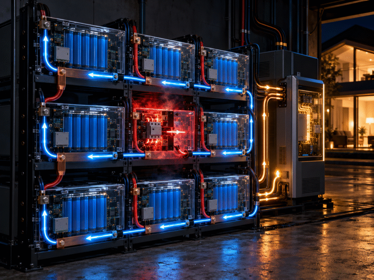
One of the most misunderstood ideas in multi-battery energy storage systems is redundancy. A customer may install four, eight or even sixteen LiFePO4 batteries and assume: “If one battery stops working, the others will simply continue and nothing will happen.”
Sometimes that is partly true. Sometimes the entire system shuts down immediately. The result depends on whether the batteries are connected in parallel, series or series-parallel, why the BMS disconnected, and whether the remaining batteries can carry the inverter load. Understanding this behavior is important for solar installers, UPS suppliers, telecom integrators and battery distributors because a system with multiple batteries is not automatically a redundant system.
First Understand the Three Connection Architectures
The electrical behavior after one battery disconnects depends heavily on the connection method.
Parallel
All batteries operate at the same nominal voltage, while total available capacity and current capability increase. Example:
4 × 51.2V 100Ah batteries in parallel create approximately:
- 51.2V nominal;
- 400Ah;
- 20.48kWh nominal energy.
Series
Battery voltages add while amp-hour capacity remains the same. Example:
4 × 12.8V 100Ah batteries in series create approximately:
- 51.2V nominal;
- 100Ah;
- 5.12kWh nominal energy.
Series-Parallel
Several batteries are first connected in series to create one string. Two or more identical series strings are then connected in parallel. Example: Four 12.8V 100Ah batteries in series create one 51.2V 100Ah string.
Two identical strings connected in parallel create approximately:
- 51.2V;
- 200Ah;
- 10.24kWh.
These three arrangements react very differently when one BMS disconnects.
What Causes a LiFePO4 BMS to Disconnect?
A BMS can interrupt charging or discharging for many reasons. Typical protection events include:
- cell overvoltage;
- cell undervoltage;
- discharge overcurrent;
- charge overcurrent;
- short circuit;
- high temperature;
- low-temperature charging;
- internal hardware fault.
A BMS trip should therefore be treated as a symptom rather than a diagnosis. Simply restarting the battery repeatedly without identifying the protection reason can hide an installation or sizing problem.
What Happens If One Battery Trips in a Parallel Bank?
Consider four 51.2V 100Ah batteries connected in parallel. If Battery 1 opens its discharge circuit but Batteries 2, 3 and 4 remain connected, the common DC bus may continue to have approximately the same operating voltage. The inverter may therefore continue running.
This sounds like excellent redundancy, but there is an important limitation. Before the trip, four batteries were sharing the load. After the trip, only three batteries remain. The current previously supplied by four batteries must now be supplied by three. This can produce a sudden increase in current through every remaining battery.
A Simple Example
Imagine a 51.2V battery system supplying a DC current of 320A to a large inverter load. With four batteries sharing reasonably evenly, each battery might supply around 80A. If one battery suddenly disconnects, the remaining three would theoretically need to supply approximately: 320A ÷ 3 = 107A per battery.
If each battery has a 100A continuous-discharge BMS limit, the remaining batteries may now also reach overcurrent protection. The sequence can become: Battery 1 trips → current rises in Batteries 2–4 → Battery 2 trips → current rises further → Batteries 3 and 4 trip → inverter shuts down.
From the customer’s perspective, it can look as though all four batteries failed at the same time. In reality, one initial trip may have created a cascading overload.
This Is Why Battery Quantity Should Not Be Sized Only by kWh
Customers frequently size an energy storage system only from required backup energy. For example: “We need 20kWh, so four 5kWh batteries are enough.”
Energy capacity is only one part of battery sizing. The system must also meet the inverter’s current requirement. A good design should consider at least:
- required usable energy;
- continuous inverter power;
- peak inverter power;
- battery BMS continuous current;
- battery peak current;
- cable current rating;
- breaker rating;
- busbar rating.
For projects where continuity is important, the designer may also consider whether the system should continue operating after one battery branch becomes unavailable. That is a different requirement from simply meeting normal operating power.
What Happens If One Battery Trips in a Series Bank?
A series-connected battery bank behaves very differently. In a series string, current passes through every battery. If one battery’s BMS opens the main current path, the series circuit is interrupted. The other batteries may still contain substantial energy, but they can no longer provide a complete path to the inverter through that string.
The inverter therefore normally loses that battery string. This means a simple series bank does not provide battery-level electrical redundancy in the same way that a parallel bank potentially can.
What Happens in a Series-Parallel Bank?
Now consider two identical series strings connected in parallel. Each string contains four 12.8V 100Ah batteries. The total system is approximately 51.2V 200Ah.
If one battery in String A trips, the entire electrical path through String A may be interrupted. String B may remain available. The system therefore changes from: 2 available strings to: 1 available string.
The inverter may continue operating only if the remaining string can safely carry the complete load. This is the key principle: In a series-parallel bank, one battery trip can remove an entire series string from service.
Why One Failed String Can Cause the Second String to Trip
Suppose each 51.2V series string is designed for a maximum continuous current of 100A. Two strings in parallel can theoretically share a 160A operating load at approximately 80A each.
If String A disconnects, String B suddenly has to provide the full 160A. If the BMS or cables are not designed for that current, String B may trip almost immediately. Again, what appears to be a complete battery-bank failure may actually be a cascading protection event caused by loss of one branch.
Redundancy Must Be Designed, Not Assumed
This is especially important for:
- telecom base stations;
- data centers;
- medical facilities;
- industrial UPS;
- security systems;
- remote off-grid sites.
If uninterrupted operation after one battery failure is a project requirement, that requirement should be defined during system design. The engineer may need to specify enough remaining battery modules to support the critical load after one module or one string becomes unavailable. This concept is similar to N+1 design used in other power systems. Installing more batteries does not automatically create N+1 redundancy unless the remaining batteries, BMS, cables and protection devices are capable of supporting the load.
What If the Battery Trips Because SOC Is Low?
Another important distinction is the reason for the trip. If one battery disconnects because of a temporary overcurrent event, it may recover after the load is removed and the BMS reset conditions are satisfied.
If a battery disconnects because one cell has already reached its low-voltage limit, repeatedly reconnecting it does not solve the underlying energy shortage. The battery may disconnect again almost immediately. If this happens repeatedly, investigate:
- actual battery SOC;
- cell voltage spread;
- load power;
- BMS current;
- battery capacity;
- inverter low-voltage setting.
A system that repeatedly reaches BMS low-voltage protection may be undersized for the required runtime or may have an unbalanced battery.
Why a Weak Battery Can Be Difficult to Find in a Large Parallel Bank
One interesting characteristic of a large parallel battery system is that healthy batteries can temporarily mask a weaker battery. At light load, all batteries may appear normal. As power increases, the weaker battery may:
- show larger voltage drop;
- provide less current;
- reach low-voltage protection earlier;
- become warmer;
- disconnect.
After it disconnects, the system may continue running, so the user does not immediately notice the problem. Later, when the load increases or another battery becomes unavailable, the system suddenly shuts down. For this reason, commercial battery systems should be evaluated at branch level rather than only by total inverter voltage.
What Should Be Monitored in a Parallel Bank?
Useful information includes:
- current of each battery;
- battery voltage;
- BMS SOC;
- cell voltage spread;
- temperature;
- alarm history;
- charge/discharge enable status.
In a larger system, a battery that repeatedly carries much less current than the others should not be ignored simply because the inverter still works.
The branch may have:
- higher connection resistance;
- a loose terminal;
- different SOC;
- BMS limitation;
- cell imbalance;
- a damaged fuse or breaker;
- different battery condition.
Why BMS Communication Becomes More Important as the System Grows
In a small battery system, a user may manually check every battery. With eight or sixteen batteries, that becomes much less practical. Many modular ESS batteries therefore use battery-to-battery communication and a master BMS. The inverter may receive information such as:
- total SOC;
- charge current limit;
- discharge current limit;
- maximum voltage;
- minimum voltage;
- battery alarms.
When one battery becomes unavailable, a properly designed system may update the available charge and discharge limits. However, communication architecture is manufacturer-specific. Users should not assume that connecting the power cables of additional batteries automatically allows the inverter to recognize their combined capacity and current capability.
Can You Switch One Parallel Battery Off While the System Is Running?
This depends on the battery system and approved operating procedure. In some modular systems, an individual branch can be isolated for maintenance while other batteries continue operating. In other systems, disconnecting a battery without following the correct communication and shutdown sequence may cause:
- communication alarms;
- incorrect battery count;
- sudden current redistribution;
- contactor stress;
- inverter shutdown.
For commercial installations, maintenance isolation should be considered during the original electrical design. Each battery branch may require an appropriate disconnect device so that service can be performed without disturbing other batteries unnecessarily.
Why Branch Protection Matters Even When Every Battery Has a BMS
A BMS provides important internal protection, but it does not replace all external DC protection. In a parallel system, several batteries are connected to the same busbar. If a fault occurs in one branch cable, current may potentially be supplied by multiple other batteries through the common bus.
Properly selected branch fuses or DC breakers therefore remain important. The protection arrangement should allow a faulty branch to be isolated while minimizing the effect on the rest of the battery bank. Protection devices must be selected for the actual DC voltage and prospective fault conditions of the system.
A Practical Question for Buyers: How Many Batteries Do I Really Need?
When requesting a quotation, instead of saying only: “I need a 30kWh lithium battery system,” provide:
- inverter rated power;
- inverter peak power;
- system voltage;
- required backup time;
- normal load;
- maximum expected load;
- required redundancy;
- inverter brand and model;
- communication protocol.
Consider a customer who needs 30kWh but also operates a large inverter. One battery configuration may provide sufficient energy but insufficient BMS discharge current. Another configuration with more parallel modules may provide the required current and better fault tolerance. This is why battery selection should consider both kWh and kW.
Frequently Asked Questions
If one parallel battery shuts down, will the inverter stop?
Not necessarily. The remaining batteries may continue supplying the inverter if they can support the required current and the control system allows continued operation.
Can one battery trip cause all the others to trip?
Yes. If the loss of one battery causes excessive current through the remaining batteries, a cascading series of BMS overcurrent trips can occur.
If one battery fails in a series string, can the other batteries keep working?
The complete series current path is normally interrupted, so that string generally becomes unavailable.
In a series-parallel system, does one battery failure remove only that battery?
Usually not. A BMS disconnection in one battery can interrupt the complete series string containing that battery.
Does adding more batteries always improve redundancy?
It can improve redundancy, but only when the remaining batteries can support the required power after one module or string becomes unavailable.
Can a battery bank be designed for N+1 operation?
Yes, depending on the battery and system architecture. The required remaining capacity, current capability, BMS behavior and communication logic should all be considered during design.
Final Thoughts
A multi-battery LiFePO4 system should never be evaluated only by total capacity. What happens when one battery disconnects depends on system topology. In a parallel bank, the remaining batteries may continue operating, but each must carry additional current.
In a series bank, one BMS opening can interrupt the entire string. In a series-parallel bank, one battery can remove one complete string, leaving the remaining strings to support the load. Understanding these behaviors helps installers avoid cascading BMS trips and helps buyers distinguish between simple capacity expansion and genuine system redundancy.
For commercial projects, designing around normal operating conditions is not always enough. The engineer should also ask what the system must do after a battery, string or communication branch becomes unavailable.
HIZN Lithium provides modular LiFePO4 batteries for solar ESS, UPS, telecom and commercial energy storage systems. For projects using multiple batteries, send us your inverter model, inverter power, system voltage, required storage capacity, expected peak load and planned battery quantity. Our team can help evaluate not only the required kWh but also parallel current capability, BMS limits, communication and expansion architecture before production.