
Introduction
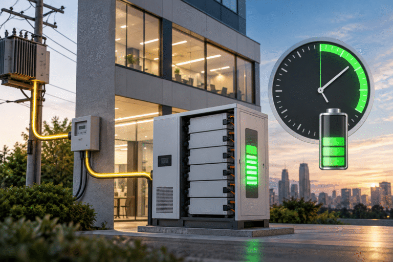
A commercial customer purchases a 50kWh LiFePO4 energy storage system with a 30kW PCS. The PCS specification suggests that the battery could charge quickly, but the building’s electrical connection has only about 10kW of spare capacity during normal operation.
The customer asks whether the battery can still use the full 30kW charger. Technically, the PCS may be capable of 30kW, but the building cannot supply another 30kW without exceeding its grid import limit, main-breaker rating or contracted demand.
This creates a common commercial ESS design problem: battery charger capacity is not the same as available site charging power.A system can have a large battery and powerful PCS while actual charging is limited by the building’s remaining electrical headroom.
Start with the Site Power Balance
Suppose a commercial building has a maximum permitted grid import of: 50kW
At a particular moment, normal building loads consume: 40kW
The theoretical spare capacity is approximately: 50kW − 40kW = 10kW
That 10kW is the maximum additional real power available before the site reaches the chosen import limit, ignoring other margins and conversion losses. Even if the PCS is rated for 30kW charging, it should not simply import another 30kW from the grid. Doing so would push total site import to approximately 70kW.
The Battery Sees Less Than the AC Spare Capacity
The 10kW available from the grid does not all become stored battery energy. The PCS has conversion losses, auxiliary electronics consume power and battery-side charging may taper at high SOC.
Suppose the PCS operates around 95% efficiency at the current load. A 10kW AC input might provide roughly: 10kW × 0.95 = 9.5kW to the battery before other small system losses are considered.
Therefore, charging-time calculations should use expected battery-side power, not just the building’s spare AC capacity.
Example: Charging a 50kWh Battery
Assume a 50kWh battery needs to charge from: 20% SOC to 90% SOC
Energy to restore is approximately: 50kWh × 70% = 35kWh
If actual average battery-side charging power is: 9kW
idealized charging time is: 35kWh ÷ 9kW ≈ 3.9 hours
Real time may be longer because power changes with building load and battery charging can slow near the upper SOC range.
This gives a more realistic answer than simply calculating: 50kWh ÷ 30kW.
A 30kW PCS Does Not Guarantee 30kW Charging
PCS nameplate power tells you what the converter can potentially process under specified conditions. It does not guarantee that the external electrical system can supply that power.
Actual charging may be limited by:
- Grid connection capacity
- Main breaker
- Transformer
- Building load
- Contracted demand
- EMS import limit
- Battery BMS current limit
- PCS temperature or kVA limit
The active charging power is always determined by the lowest applicable limit.
Building Loads Change Continuously
A fixed 10kW spare-capacity assumption may not be valid throughout the day.
At 09:00, the building may use 35kW, leaving 15kW spare. At noon, HVAC and production equipment may raise load to 48kW, leaving only 2kW. At midnight, building load may fall to 10kW, leaving 40kW of electrical headroom.
The battery can therefore charge at very different rates at different times. This is why commercial ESS often benefits from dynamic load-following charging.
What Is Dynamic Charging?
Dynamic charging means the EMS continuously monitors building power and adjusts the PCS charging command so that total grid import stays below a defined limit.
Suppose the import limit is 50kW. If building load is 25kW, the EMS may allow 20kW or more of battery charging while retaining margin.
If building load rises to 45kW, the EMS reduces battery charging to perhaps 3–5kW. When the load falls again, charging power increases automatically. This allows the ESS to use available grid capacity without tripping the main breaker or exceeding a demand target.
Static Charging Limits Are Simpler but Less Efficient
An alternative is to configure one fixed charging limit, perhaps 8kW, based on the worst normal building load.
This is easy to implement but can waste available capacity. During periods when the building load is low, the battery still charges at only 8kW even though much more power is available.
For a site with a large battery and short charging window, dynamic control can significantly improve recovery.
Main-Breaker Rating Is Not Always the Same as the Operating Limit
A building may have a main breaker that physically allows 100kW equivalent demand, but the customer may deliberately limit import to 70kW because of utility contract conditions or demand charges.
Therefore, the EMS charging limit may be lower than the electrical hardware maximum. Commercial ESS design should clarify whether the constraint comes from: physical infrastructure or economic operating strategy. The solution may differ.
Demand Charges Can Make Fast Charging Expensive
In some electricity markets, commercial users pay charges based partly on their maximum demand during a billing period.
Suppose the site’s normal monthly peak is 300kW. Charging a large battery at 100kW during an already high-load period could raise grid demand to 400kW and increase the customer’s demand charge.
Paradoxically, the battery installed to reduce energy costs can increase them if its charging schedule is poorly designed. A good EMS therefore considers electricity price and demand peak, not just battery SOC.
Charging at Night Can Be Much More Practical
If building load is low overnight, the available grid capacity can be dramatically higher.
Consider the same site:
Daytime building load: 40kW
Nighttime building load: 10kW
Grid import limit: 50kW
Daytime spare capacity: 10kW
Nighttime spare capacity: 40kW
If the PCS is rated for 30kW, the battery may charge at only around 10kW during the day but reach the full 30kW PCS rating at night. The battery and charger have not changed. Only site headroom changed.
Time-of-Use Tariffs Strengthen the Case
Many commercial customers already prefer overnight charging because electricity is cheaper at off-peak times. If the same period also has lower building load, the economic and electrical incentives align.
The ESS can charge faster without raising the building’s daily peak demand. A properly designed schedule should still leave room for solar charging if significant PV production is expected the next day.
Solar Can Reduce Grid Charging Requirements
A building with rooftop PV may use grid charging only to reach a minimum morning reserve, then allow solar to complete the battery charge.
For example, a 50kWh battery might charge overnight from 20% to 50%, leaving approximately half the battery available to absorb daytime solar surplus.
This can avoid unnecessary grid import and reduce solar curtailment. The optimal strategy depends on load, weather, electricity tariff and backup reserve requirements.
The EMS Can Use Both Grid Limit and Solar Forecast
More advanced systems can combine dynamic import control with weather or PV forecasting. If the next day is expected to be sunny, the system may intentionally leave more battery headroom overnight.
If heavy clouds are forecast and backup reserve is important, the EMS may charge the battery further from the grid. This turns charging from a fixed electrical setting into an energy-management decision.
Example: 50kWh ESS at a Small Factory
Suppose a factory has:
- 50kWh battery
- 30kW PCS
- 60kW grid import limit
- 45kW daytime production load
- 15kW nighttime load
During production hours, only around 15kW of grid headroom remains before margin and losses. At night, approximately 45kW of headroom exists, so the 30kW PCS becomes the limiting device. The most efficient strategy may therefore be to use limited daytime charging and perform major recovery overnight.
BMS Current Can Still Override the Site Limit
Suppose the grid and PCS could provide 30kW, but the battery is near full and its BMS reduces Charge Current Limit. Actual power may fall to 10kW or lower.
The EMS must respect the BMS even when plenty of grid power is available. Commercial charging therefore involves at least three layers of control: site limit → PCS limit → battery limit The lowest allowed value becomes the real charging power.
Battery Voltage Determines the Current Required
A 30kW charging command on a 51.2V low-voltage battery system implies very high DC current.
At approximately 55V: 30,000W ÷ 55V ≈ 545A
This may require several parallel battery modules and large DC busbars. The same 30kW on a 500V high-voltage battery requires only around 60A. This is one reason larger commercial ESS often uses high-voltage battery architecture.
A Large PCS on a Small Battery Can Be Poorly Matched
Suppose a customer installs a 30kW PCS with only one 51.2V 100Ah battery. The battery may have neither the current capability nor energy capacity to use the PCS meaningfully.
The grid connection may not be the only bottleneck. Battery power capability must be checked independently. PCS sizing should follow both the facility’s power requirement and the battery’s approved charge/discharge capability.
Transformer Capacity Can Limit Charging
A facility may have sufficient utility contract capacity but an internal transformer already operating near its thermal limit. Battery charging adds another sustained load to that transformer. Unlike a short motor-start event, charging can continue for hours.
Commercial ESS engineering should therefore review transformer loading under the proposed charging schedule. A system that stays below the main breaker rating can still overload another upstream component.
Long Charging Sessions Are Continuous Loads
Battery charging differs from many intermittent building loads because it can remain near maximum power for extended periods.
A 20kW charger operating for four hours places a sustained load on:
- Transformer
- Cables
- Switchgear
- PCS
- Cooling system
Thermal design should consider continuous operation rather than only short-duration peak current. This is particularly important in hot electrical rooms.
EV Chargers Can Compete with ESS Charging
Modern commercial sites increasingly combine battery storage with EV charging. If an EV charging station draws 40kW while the ESS also attempts 30kW grid charging, total site demand can rise sharply.
A coordinated EMS can prioritize the two loads according to schedule and business needs. For example, ESS charging may temporarily decrease when several EVs connect. Without coordination, the main service becomes the bottleneck.
Heat Pumps and HVAC Create Similar Conflicts
Buildings with large electric HVAC systems can have strong seasonal demand variation. A charging strategy designed during mild spring weather may fail in summer when air-conditioning consumes much more power.
Dynamic import control adapts automatically, while a poorly chosen fixed charging schedule may repeatedly approach the building limit. Commercial ESS commissioning should ideally review several operating seasons or use historical load data.
Historical Load Profiles Are Extremely Valuable
Before selecting charger or PCS power, ask for the site’s 15-minute or hourly load data if available. This reveals how much spare capacity actually exists throughout the day.
A site whose average load is 30kW may still peak at 70kW every afternoon. Sizing from monthly average consumption alone can therefore produce unrealistic charging assumptions. The battery project should be based on the real load profile.
Required Recharge Time Should Be Defined
Instead of asking only, “How much grid power is available?” ask: How quickly does the battery need to recover?
A 50kWh battery used mainly for solar shifting may have all night to charge. A backup battery in an unreliable-grid region may need rapid recovery between outages.
If the customer requires 35kWh restored in two hours, average battery-side charging power needs to exceed approximately 17.5kW before losses and taper are considered. If the building can spare only 10kW, the requirement cannot be met without changing something else.
Possible Solutions When Grid Headroom Is Too Small
If the building cannot provide enough charging power, several options exist. Charging can be shifted to low-load hours, non-essential loads can be scheduled differently, PV can contribute to recovery, charger power can be dynamically controlled or electrical infrastructure can be upgraded.
Increasing battery capacity alone does not solve insufficient charging power. In fact, a larger battery may increase recovery time if the same site power limit remains.
Backup Reserve Can Reduce the Required Recharge Amount
Suppose the customer normally cycles only between 30% and 80% rather than fully depleting the battery. The amount of energy that needs to be restored each day becomes smaller, reducing the charging-power requirement.
Operating SOC strategy can therefore help match a large battery to a limited grid connection. However, the chosen SOC window must still satisfy backup requirements.
Example: A Practical Calculation
A 50kWh battery starts at 30% SOC and needs to reach 80%.
Energy to restore: 50kWh × 50% = 25kWh
The site has an average of 8kW spare grid capacity during the available charging window.
Assuming about 7.5kW reaches the battery on average after conversion losses: 25kWh ÷ 7.5kW ≈ 3.3 hours
If the charging window is four hours, the requirement is feasible. If the site requires the same recovery in two hours, the available grid capacity is insufficient.
What Data Should an EPC Contractor Request?
Before sizing a commercial ESS charger, collect battery capacity, PCS power, grid-service capacity, transformer rating, main-breaker rating, historical site load, maximum demand target, PV capacity, charging window and desired SOC range.
This allows the charging strategy to be designed from actual facility constraints. A commercial ESS quotation based only on “50kWh battery + 30kW inverter” is incomplete.
Commissioning Dynamic Import Control
After installation, test the EMS under changing building loads. Start battery charging at a controlled power level, then introduce a significant site load where practical and safe.
Confirm that battery charging decreases as expected while grid import remains below the configured limit. When the site load is removed, charging should increase again without instability. This verifies that the battery system is coordinating with the building rather than operating as an independent charger.
Conclusion
A 50kWh LiFePO4 ESS can be paired with a 30kW PCS and still charge at only 5kW or 10kW if the building has limited spare grid capacity. Actual charging speed depends on site load, grid import limit, transformer and breaker capacity, PCS power, conversion losses and BMS charging limits.
For commercial projects, charger sizing should therefore begin with the building’s real load profile and required recovery time—not only the battery kWh.
HIZN supplies LiFePO4 battery solutions for commercial, industrial and solar energy storage applications.
For a commercial ESS project, send us the battery capacity, PCS power, building grid capacity, typical load profile and required charging window. We can help calculate the battery-side charging requirement and identify whether site power availability is likely to become the limiting factor.