
Introduction
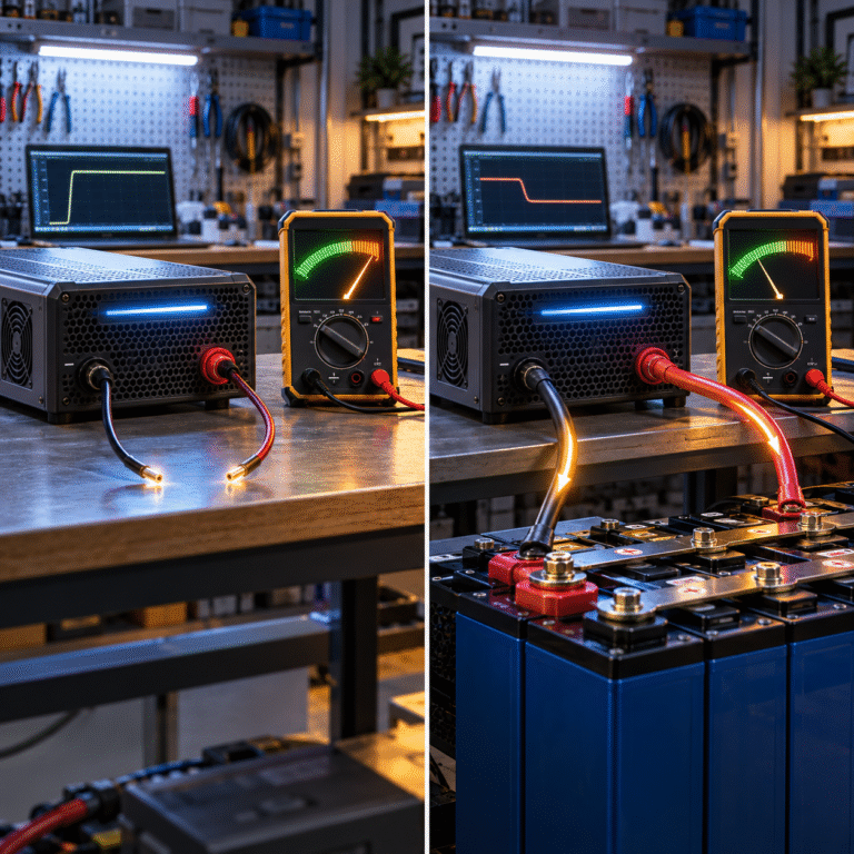
A technician checks a LiFePO4 charger with a multimeter and sees 56.8V at the output terminals. Everything appears correct. The charger is then connected to a partially discharged 51.2V battery, and the measured voltage immediately falls to 52.5V while a substantial charging current begins to flow.
The customer becomes concerned because the charger’s label says 56.8V. They may assume that a properly functioning charger should maintain exactly 56.8V throughout the entire charging process. In reality, this behavior can be completely normal for a constant-current/constant-voltage charger.
A charger’s rated charging voltage is usually its upper voltage target, not necessarily the voltage it will force onto the battery from the first second of charging. To understand whether the charger is operating normally, it is necessary to look at voltage, current and power together.
The Battery Determines the Initial Terminal Voltage
Suppose a partially discharged 51.2V LiFePO4 battery is resting at approximately 52V. When a properly designed charger is connected, the battery does not instantly jump to 56.8V. Instead, the charger begins supplying current while the battery voltage gradually rises according to its SOC, charging current, internal resistance and cell condition.
During the early part of charging, the charger may be operating in constant-current mode. The charger regulates current to the configured value while allowing its output voltage to settle at whatever level is required to push that current into the battery. If the battery is currently around 52V, a measured output voltage near that level is therefore expected.
The voltage only approaches the charger’s upper target as the battery becomes more charged.
56.8V May Be the CV Limit, Not the Starting Voltage
A typical LiFePO4 charger follows a CC/CV strategy. CC stands for Constant Current, while CV stands for Constant Voltage. During the CC stage, the charger supplies the allowed current and battery voltage gradually increases. Once the target voltage is reached, the charger enters the CV stage and holds approximately that voltage while current decreases.
A simplified charge sequence might look like this:
| Charging Stage | Battery Voltage | Charging Current | Charger Behavior |
|---|---|---|---|
| Early charge | 51.5–53V | High | Current limited |
| Mid charge | 53–55V | High | Current limited |
| Near full | Approaches target | Begins falling | Transition to CV |
| Final stage | Near charge target | Low | Voltage limited |
The exact values depend on the battery and charger. The important point is that a charger labeled 56.8V does not need to show 56.8V throughout the entire process.
Why Open-Circuit Voltage Can Be Misleading
Measuring a charger with no battery connected tells you whether the charger can produce voltage, but it does not prove that it can deliver its rated power. A charger may show the correct open-circuit voltage even when it has a problem that becomes visible only under load.
This is similar to testing a weak power source without connecting anything to it. The voltage may look perfect because almost no current is flowing. Once a large load is connected, the voltage may collapse if the power source cannot provide the required current.
Therefore, an open-circuit voltage test is useful, but it is only the beginning of charger diagnosis.
Normal Voltage Reduction vs Abnormal Voltage Collapse
The key is to distinguish between a normal CC charging voltage and an abnormal output collapse. Suppose the battery is at 52.0V and the charger begins delivering 50A while voltage stabilizes around 52.6V. If the current remains stable and battery voltage gradually rises over time, the charger is probably operating normally.
Now consider a different case. The charger reads 56.8V with no battery attached, but once connected the voltage collapses to 46V, current repeatedly falls to zero and the charger restarts. That behavior is much more likely to indicate an input-power problem, protection event, charger fault or incorrect battery connection.
Do not diagnose the charger using voltage alone. Always ask what charging current is flowing at the same time.
Current Limit Can Intentionally Pull the Voltage Down
Suppose a charger is rated for 50A. The battery is at a relatively low SOC and would accept much more current if available. The charger protects itself by limiting output to 50A.
To maintain only 50A, the charger does not need to force the battery to its final charge voltage immediately. It allows the battery terminal voltage to follow the normal charging curve while holding current near 50A. As SOC increases, battery voltage gradually moves upward until it reaches the CV target.
This is normal power-converter control, not a voltage-regulation failure.
Charger Power Limit Creates Another Restriction
Many chargers have both a maximum current and a maximum power rating. Suppose a charger is rated for 5kW and 100A. At 52V, delivering 100A would require approximately 5.2kW, so the charger may already be close to or above its power limit.
The controller might therefore reduce current slightly. At 56V, 5kW corresponds to only around 89A. Even though the charger has a 100A maximum-current specification, the 5kW power limit can prevent it from providing 100A at the higher battery voltage.
When troubleshooting, compare three ratings rather than one: maximum DC voltage, maximum DC current and maximum DC power.
The AC Input Can Cause the DC Voltage to Collapse
A charger cannot produce stable DC power if the AC supply feeding it is weak. This is especially relevant when charging from generators, long extension cables or weak utility grids.
For example, an AC charger may operate normally at 230V with no load. When charging begins, input current rises and the site voltage falls to 195V because the supply cable is undersized. The charger may then reduce output power, enter undervoltage protection or repeatedly restart.
From the battery side, the customer sees low charging voltage and low charging current. The actual problem is upstream on the AC side.
When charger output is unexpectedly weak, measure AC input voltage while the charger is delivering significant power, not only before charging begins.
Generator Charging Can Expose This Problem
Generator-powered charging is particularly sensitive because the generator must simultaneously maintain voltage, frequency and enough real power for the charger. A charger may draw several kilowatts continuously, and other site loads may start at the same time.
If the generator is too small, the sequence may be: charger starts, AC voltage drops, charger derates, generator voltage recovers, charger increases power again, and the process repeats. The customer may mistakenly interpret this as unstable battery charging.
A correct diagnosis should compare generator output, AC charger input and battery-side DC data at the same time.
Charger Temperature Can Also Reduce Output
Power electronics generate heat during charging. If the charger becomes too hot, internal thermal protection may reduce its output current or power. In this case, voltage may rise normally at first, but charging current gradually decreases after the charger has operated for an hour.
This can be especially noticeable in electrical cabinets with poor airflow or installations in hot climates. A charger rated for a particular output under normal laboratory conditions may have a lower permissible output at high ambient temperature.
Check whether the manufacturer provides a temperature derating curve before assuming the battery is limiting current.
Cable Voltage Drop Can Make Two Measurements Different
Another source of confusion appears when charger voltage and battery voltage are measured at different physical points. Imagine the charger terminals show 53.5V while the battery terminals show 53.0V during an 80A charge. The 0.5V difference may be caused by resistance in the DC cables, breakers, fuse holders and terminals.
The difference should decrease when charging current decreases. If a large voltage difference exists only at high current, cable resistance is a strong possibility.
Measure voltage directly at both ends under load. Do not compare a charger display reading during charging with a battery voltage measured ten minutes later after current has stopped.
BMS Charge Limits Can Make the Charger Appear Weak
A communicating battery may tell the inverter or charger to reduce current. For example, the charger hardware may support 100A, but the BMS may currently request only 30A because a cell is approaching its upper voltage limit.
The charger then follows the BMS command. From the customer’s perspective, the charger appears unable to reach its rated current, but it is actually responding correctly to the battery.
Check BMS values such as SOC, highest cell voltage, temperature and Charge Current Limit before concluding that the charger has failed.
Example: A Normal 51.2V Charging Session
Consider a 51.2V 200Ah battery connected to a charger whose upper charging target is 56.8V and whose current limit is 40A. The battery begins at 30% SOC and approximately 52V.
During the first several hours, current may remain close to 40A while pack voltage slowly increases from approximately 52V toward the upper range. The charger is not “missing” 4V during this period. It is intentionally operating in constant-current mode.
Near the end, voltage approaches 56.8V. The charger begins holding voltage rather than current, and current gradually drops below 40A. This is normal CC/CV operation.
Example: A Situation That Deserves Investigation
Now imagine the same charger connected to the same type of battery. Open-circuit output is 56.8V, but once connected, the charger produces only 2A and its output voltage repeatedly fluctuates between 48V and 54V.
At the same time, the battery SOC is only 30%, BMS temperature is normal and no charging-current limit is active. In this situation, check AC input voltage, charger alarms, connector condition and DC protection devices. A healthy charger should normally be capable of much more stable output under these conditions.
A Practical Troubleshooting Procedure
When the charger voltage appears to fall after connection, record the complete operating condition rather than one number. Useful data includes:
- Charger model and rated DC output
- AC input voltage while charging
- Battery SOC
- Battery pack voltage
- Charging current
- Battery temperature
- BMS Charge Current Limit
- Highest and lowest cell voltage
- Charger alarm or derating status
- DC cable size and length
The most useful test is usually performed while the fault is happening. Measurements taken after the charger has been disconnected often hide the actual cause.
Do Not Raise the Charger Voltage to “Fix” a Normal CC Stage
One of the worst responses to this situation is to see only 53V while charging and increase the charger’s target from 56.8V to a much higher number. If the charger is already operating correctly in CC mode, the higher setting does nothing useful during early charging but can create excessive voltage later when the battery approaches full SOC.
Charging voltage should remain within the battery manufacturer’s specification. Low measured voltage during early constant-current charging is not a reason to raise the upper limit.
Conclusion
A LiFePO4 charger showing 56.8V with no battery attached and approximately 52–55V after connection is not automatically defective. In many cases, this is exactly what a CC/CV charger should do while supplying a partially discharged battery with controlled current.
The correct diagnosis requires looking at voltage, current and power together. If charging current is stable and battery voltage gradually increases, the charger is probably functioning normally. If both voltage and current collapse, then AC input quality, charger power limits, thermal derating, cables and BMS restrictions should be investigated.
HIZN supplies LiFePO4 batteries for residential solar, telecom, commercial and off-grid energy storage applications with model-specific charging parameters and BMS communication options.
If a charger shows the correct voltage when disconnected but behaves differently after connection, send us the battery model, charger model, SOC, battery voltage, charging current and AC input voltage. These values can help determine whether you are seeing normal CC charging or a real power-system problem.