
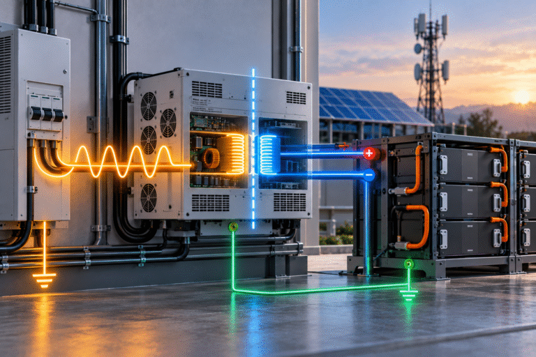
What Does Galvanic Isolation Mean?
Galvanic isolation means there is no direct conductive electrical path between two circuits. Energy can still be transferred through mechanisms such as: transformer coupling.
For an isolated AC/DC charger, the AC input and battery-side DC output are separated by an isolation barrier designed to the equipment’s safety requirements. A non-isolated converter does not provide the same separation. This difference affects how the battery DC bus relates electrically to the AC supply and earth.
Isolation Is Not the Same as Turning the Charger Off
A disconnected switch can interrupt current, but galvanic isolation refers to the electrical architecture of the converter itself. It is a designed insulation barrier with specified ratings.
Whether isolation is required depends on: the application, system topology, local standards and other connected equipment. It should not be added or removed casually in the field.
What Is a Floating DC Bus?
A DC battery system is often called: floating when neither the positive nor negative conductor is intentionally bonded directly to protective earth at the battery bus.
The DC bus still has: positive and negative voltage between its conductors. But its relationship to earth is not intentionally fixed at one pole.
Floating systems are common in some industrial, telecom and UPS architectures because they can support insulation monitoring and fault detection strategies.
Floating Does Not Mean “Ungrounded and Unsafe”
This terminology can be misunderstood.
A floating DC bus may still have: protective-earth bonding of metal enclosures, equipment chassis and other safety components.
What remains floating is the active DC circuit relationship to earth, depending on system design. Protective grounding and functional DC pole grounding are different concepts.
What Is Negative Ground?
Some DC systems intentionally bond: battery negative to a reference or earth point.
Other systems may use: positive grounding.
Traditional telecom architectures, vehicle systems and industrial equipment can use different conventions. The correct arrangement depends on the complete system.
It is not safe to assume: All 48V battery negatives should be grounded.
or: Lithium batteries should always float. Neither statement is universally correct.
The Charger Can Change the Grounding Architecture
Suppose a battery bus is intended to remain floating.
A non-isolated charger connected to another grounded system may unintentionally create a reference path between the DC bus and earth.
Now the battery is no longer behaving as the designer intended. This can affect: insulation monitoring, leakage current and fault diagnostics.
Therefore, charger topology matters in systems with controlled grounding requirements.
Why Isolation Can Be Valuable
Galvanic isolation can provide separation between: AC source and battery DC bus.
Depending on system design, this can help with: ground-loop management, DC bus architecture, fault containment and compatibility with floating systems.
However, isolation is not automatically superior in every application.
It can add: cost, size, conversion stages and design complexity. The correct choice depends on system requirements.
Non-Isolated Converters Have Advantages Too
Non-isolated power converters can offer: high efficiency, lower cost, smaller size and high power density.
Modern hybrid inverters and PCS systems may use non-isolated topologies as part of a complete certified architecture. A non-isolated charger is not automatically unsafe or low quality.
The key question is: Is the topology appropriate for the complete installation?
Never Evaluate the Charger in Isolation from the Inverter
A battery may simultaneously connect to: charger, inverter, MPPT controller, monitoring equipment and communication devices.
Each device can influence the DC bus relationship to ground. For example, one device may be isolated while another is not.
The overall system may therefore be non-isolated even though the battery charger itself uses an isolation transformer. System grounding must be evaluated as a whole.
Two Isolated Devices Do Not Automatically Create a Correct Grounding Scheme
Likewise, installing multiple isolated components does not automatically guarantee that the system is safe or correctly referenced.
The project still needs a defined: earthing, bonding and fault-protection strategy. The charger specification is only one piece of that design.
Why This Matters in Telecom Systems
Telecom DC power systems often have established grounding and bonding practices. When replacing traditional VRLA batteries with LiFePO4, the battery may be installed into an existing: rectifier system, DC distribution frame and monitoring network.
The lithium battery supplier should understand whether the site uses: floating or referenced DC architecture and ensure that the battery/BMS communication interfaces are compatible with that arrangement.
Communication Ports Can Create Hidden Paths
Even if the charger power stage is isolated, communication cables can sometimes create another electrical relationship.
Interfaces may include: RS485, CAN, RS232, Ethernet or USB.
Some communication ports are isolated. Others share device ground. Connecting multiple devices through non-isolated communication ports can create unexpected ground paths.
This is why industrial communication design sometimes specifies isolated communication interfaces.
CAN Isolation Can Matter in Large ESS
In a simple battery-inverter installation with short cables, standard CAN may work well. In larger systems with:
multiple racks, PCS, EMS and long cable runs, isolated CAN interfaces can improve robustness and reduce ground-potential issues depending on system architecture.
Battery communication requirements should therefore be included in the integration design, not treated as an afterthought.
RS485 Grounding Also Requires Care
RS485 is a differential communication standard, but real-world installations still need correct: reference, shielding and termination. Connecting shields or signal grounds incorrectly can create: noise or unwanted current paths.
Follow the battery and inverter manufacturer’s approved communication wiring. Do not improvise grounding solely from connector appearance.
Protective Earth Is Different from Battery Negative
This distinction is crucial. Protective earth is intended for equipment safety. Battery negative is one conductor of the DC power circuit.
They may be connected at a defined point in some systems. They may remain electrically separate in others. Treating them as automatically interchangeable can defeat the designed protection architecture.
Chassis Bonding Still Matters
Even when the battery DC bus is floating, metal enclosures may still require protective bonding according to equipment design and local electrical rules.
Floating active conductors do not mean: leave the cabinet metal unprotected. The grounding system should follow: equipment manufacturer instructions and applicable electrical standards.
Isolation Monitoring in High-Voltage ESS
As battery systems move from: 51.2V
to: hundreds of volts DC, insulation monitoring becomes increasingly important.
A high-voltage ESS may use an: Insulation Monitoring Device (IMD) to measure insulation resistance between the high-voltage DC bus and chassis/earth.
An unintended grounding path through a charger or auxiliary device can interfere with this monitoring strategy. This is one reason high-voltage ESS integration requires detailed electrical coordination.
A Floating HV Bus Can Detect the First Insulation Fault
In some high-voltage architectures, the DC system intentionally remains isolated from earth while an IMD monitors insulation condition.
If one pole develops leakage toward chassis, the monitoring system detects the reduction in insulation resistance. The system can then alarm or respond according to its safety design. Connecting an incompatible grounded device can change this behavior.
Do Not Apply High-Voltage ESS Logic Directly to 48V Systems
High-voltage commercial ESS and low-voltage residential batteries operate under very different: electrical, regulatory and safety conditions.
Concepts such as isolation monitoring may be essential in one design but unnecessary in another. System voltage and application context matter.
Why Marine and Vehicle Systems Can Be Different
Mobile systems may connect batteries to: vehicle chassis, alternators, shore chargers and DC-DC converters.
A shore-powered charger can introduce a connection between: external AC supply and onboard DC system.
Isolation requirements may therefore differ from a stationary solar installation. Marine applications may have additional concerns involving corrosion and shore-power grounding. Use application-specific equipment.
DC-DC Chargers Can Provide Isolation—or Not
A DC-DC charger may be: isolated or non-isolated.
For example, a vehicle charging system may use a non-isolated charger sharing a common negative. Another installation may require fully isolated input and output.
Do not assume all DC-DC chargers behave the same just because their voltage ratings are identical.
Why Industrial Buyers Ask for Isolation Voltage
Professional charger specifications may include values such as: input-to-output isolation rating or dielectric withstand voltage.
This describes part of the equipment insulation design. It is different from: normal operating battery voltage.
A 51.2V battery charger can have a much higher insulation test rating between AC input and DC output.
Isolation Rating Should Come from Certification, Not Guesswork
Do not use: transformer size, enclosure appearance or marketing photographs to determine whether a charger is truly isolated.
The manufacturer should provide: topology information where applicable and relevant safety/certification specifications.
For project procurement, request documented ratings.
Does Isolation Improve Charging Performance?
Not necessarily. Isolation does not automatically make a battery: charge faster or reach higher SOC.
Charging performance still depends on: output voltage, current, regulation, communication and battery BMS.
Isolation is mainly a system-integration and safety architecture issue.
An Isolated Charger Can Still Be Configured Incorrectly
A charger may have excellent galvanic isolation but: wrong charging voltage or excessive current.
It would still be unsuitable. Isolation does not replace basic LiFePO4 compatibility checks.
A Non-Isolated Charger Can Be Completely Appropriate
Likewise, a certified non-isolated inverter/charger can be correct when: the entire system is designed around that topology.
The question is not: Is isolated always better?
The question is: What does the complete system require?
Ground Loops Can Cause Communication Problems
If several devices create multiple ground paths, small circulating currents can flow. This can contribute to: communication noise, measurement offsets and unexpected behavior.
For B2B projects with: battery racks, multiple inverters and SCADA systems, grounding and communication isolation should be reviewed during design.
Current Sensors Can Also Depend on Architecture
BMS systems may use: shunt sensors or Hall-effect sensors. Measurement architecture can interact differently with grounding and isolation.
For example, Hall sensors can measure current without inserting a direct electrical measurement path in the same way as a shunt. However, sensor selection is only one part of overall BMS design.
Leakage Current Is Not the Same as a Short Circuit
Power-electronic equipment can have small leakage currents due to: EMI filters and parasitic capacitance.
These currents may be normal within equipment design limits. But excessive or unexpected leakage can affect:
RCD/GFCI behavior, insulation monitoring or touch-current requirements.
Professional system design must distinguish: normal equipment leakage from an actual insulation fault.
Why EMI Filters Create Earth Relationships
Many AC chargers include electromagnetic-interference filters. These can contain capacitive connections to protective earth. Therefore, even an isolated power stage may show certain AC leakage characteristics.
This is normal engineering behavior when within design limits. It illustrates again why a simple multimeter continuity test is not enough to fully characterize charger isolation.
Do Not Modify Internal Grounding to “Fix” a Measurement
A user may measure unexpected voltage between: battery negative and earth and decide to add a jumper.
This can be dangerous because the voltage may result from: filter capacitance or floating-circuit behavior. Adding an unapproved bond can defeat: fault protection, insulation monitoring or manufacturer design.
Grounding changes should only follow the approved electrical design.
What Should Be Defined in a B2B Project?
For telecom, UPS or industrial ESS, the technical specification should define: DC system voltage, AC input supply, whether the DC bus is floating or referenced, protective-earth requirements, charger isolation requirement, BMS communication interface and monitoring requirements.
These questions should be resolved before equipment is purchased.
Example: Telecom Rectifier Replacement
An operator replaces an older rectifier system. The existing site uses a defined DC grounding architecture.
The new rectifier must match: output-voltage requirements and grounding behavior.
Selecting solely by: “48V 100A” is insufficient.
The supplier should review how the new rectifier interfaces with: battery negative, site earth and telecom distribution.
Example: High-Voltage Commercial ESS
A battery rack operates at several hundred volts DC. It communicates with a PCS and uses insulation monitoring. An auxiliary charger, service power supply or measurement device is later added.
If that device creates an unintended earth reference, insulation monitoring behavior may change. This is why auxiliary equipment in HV ESS must be approved for the system architecture.
How Battery Suppliers Can Help
A battery supplier does not necessarily design the complete site grounding system. But it should provide relevant information such as: battery terminal architecture, chassis grounding requirements, BMS communication isolation where applicable and inverter/PCS integration requirements.
The EPC contractor then coordinates these with local electrical design.
Questions to Ask the Charger Supplier
A professional project may need to confirm whether the charger is isolated, its input-to-output insulation rating, whether DC negative is internally bonded to earth, the communication-port isolation arrangement and any required protective-earth connection.
These details can prevent integration problems later.
Questions to Ask the Battery Supplier
Useful battery-side questions include: whether the enclosure requires PE bonding, whether battery negative is internally connected to chassis, whether CAN/RS485 ports are isolated and whether any grounding architecture is required for BMS operation.
Again, exact answers depend on the product.
Residential Projects Should Not Be Overcomplicated
For standard residential ESS installations using an approved battery and compatible hybrid inverter, users generally should not redesign the internal grounding architecture.
Follow: manufacturer installation instructions and local electrical code.
The isolation discussion becomes most important when integrating products from different suppliers or building industrial custom systems.
Commercial Projects Need an Interface Document
For larger ESS, create an electrical interface specification that defines: battery voltage range, PCS voltage range, grounding concept, isolation requirements, communication, protective devices and start-up sequence.
This is much better than discovering grounding incompatibilities during site commissioning.
Safety Is a System Property
No single component can guarantee that an installation is safe. An isolated charger may be connected incorrectly. A non-isolated PCS may be perfectly safe within its certified architecture.
The final result depends on: equipment design, wiring, grounding, protection and installation. This is why charger isolation should be evaluated as part of the complete ESS.
Conclusion
A LiFePO4 charger does not always need galvanic isolation, and isolation is not automatically superior in every application. What matters is whether the charger’s electrical architecture matches the complete system.
For residential solar, this is usually handled by the approved inverter/battery installation design. For telecom, UPS, marine and commercial ESS, engineers may also need to consider: floating DC buses, intentional pole grounding, protective earth, communication isolation and insulation monitoring.
HIZN supplies LiFePO4 energy storage batteries for low-voltage and larger ESS applications with CAN/RS485 communication options.
If your project uses an industrial rectifier, UPS charger or third-party PCS, send us the battery voltage, charger/PCS model and system application. We can help identify the battery-side interface information that should be confirmed before final electrical integration.