
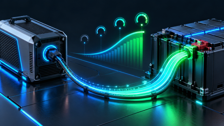
Why Not Apply Maximum Current Immediately?
Power electronics contain capacitors, inductors, semiconductor switches and protection circuits. When the charger first starts, several electrical conditions are changing at the same time. Applying maximum current instantly can create unnecessary stress on the charger, AC supply and battery connections.
A controlled ramp allows the system to stabilize first. The charger can confirm that the battery is present, voltage is within range and no protection condition exists before increasing current toward the configured target.
This is particularly useful in high-power systems where an abrupt load step on the AC side could cause utility voltage sag or generator instability.
Soft-Start Is Different from Battery Precharge
These two terms are related but not identical. Precharge usually refers to charging the DC-link capacitors of an inverter or PCS before a main contactor closes. Soft-start generally describes the gradual increase of converter output after the electrical connection has already been established.
A system can therefore perform precharge first and current ramping second. For example, the battery may precharge the inverter DC bus, close the main contactor and then allow the inverter charger to increase battery current gradually from 0A to 100A.
When diagnosing startup behavior, it is useful to determine whether the current delay occurs before or after the main DC connection is established.
AC Input Qualification Can Delay Full Charging
Before an inverter begins high-power grid charging, it may verify that the AC source is stable. The controller can check voltage, frequency and other operating conditions for a defined period before increasing charger power.
This is especially important in weak-grid and generator applications. If the charger immediately demanded several kilowatts from an unstable source, AC voltage could collapse. A gradual ramp lets the converter observe how the source responds.
For example, a charger may begin at 10% power, then increase progressively as long as AC voltage remains within its approved range. If voltage begins to sag, it can stop increasing before the upstream breaker or generator becomes overloaded.
Generator Charging Often Uses a Slower Ramp
Generators are more sensitive to sudden load changes than strong utility grids. A large charger can represent a substantial step load, particularly when other site equipment is already operating.
A soft-start sequence gives the generator governor and voltage regulator time to respond. Instead of jumping instantly from a small load to an additional 5kW or 10kW, the charger may increase power over several seconds.
This can improve generator stability and reduce frequency or voltage excursions during battery recovery.
BMS Communication May Be Part of the Startup Sequence
In a closed-loop LiFePO4 system, the inverter may wait for valid CAN or RS485 data before allowing full charging current. During startup, it can confirm SOC, pack voltage, Charge Current Limit, Charge Voltage Limit, temperature and alarm status.
Until that data is considered valid, the inverter may use a conservative current. Once communication is established and the BMS reports a higher permissible value, charging current increases.
This means a delayed current ramp can sometimes indicate normal BMS handshaking rather than an electrical limitation.
What Happens If BMS Communication Is Slow or Intermittent?
If the communication link takes unusually long to become stable, the inverter may remain at a reduced current for longer than expected. If communication repeatedly drops and reconnects, the charger may repeatedly reduce power and ramp up again.
The customer may describe this as “charging current keeps climbing and falling.” In that case, the important question is whether the behavior occurs only once during startup or continues throughout the charging session.
One smooth ramp after startup is often normal. Repeated ramps combined with communication alarms deserve further investigation.
Temperature Checks Can Also Delay Current
Some BMS designs evaluate cell temperature before allowing full charging. If the battery has just powered on, temperature sensors and control logic may require a short stabilization period.
Similarly, a charger that was previously operating at high power may begin a new charging session at reduced output if its internal electronics remain hot. As temperature stabilizes, it may allow more power.
The exact behavior depends on charger and BMS design, but temperature should be considered when current ramping changes according to time of day or ambient conditions.
Current Ramping Protects the AC Side Too
Suppose a 5kW charger is connected to a single-phase AC supply. At full output, it may draw more than 20A depending on input voltage, efficiency and power factor.
An instantaneous transition from almost zero input current to more than 20A can create a noticeable voltage step on a weak circuit. Gradual ramping reduces the size of that electrical transition.
This is one reason a charger may behave differently when connected to a strong utility panel versus a long extension cable or undersized generator supply.
Example: A Normal 100A Startup
Consider a 51.2V battery and an inverter charger configured for a maximum of 100A. The battery is at 40% SOC, temperature is normal and the BMS allows 100A.
The charging sequence might begin at 10A, increase to 30A after a few seconds, then 60A and finally settle near 100A. If battery voltage rises normally, no alarms are present and current remains stable afterward, the ramp is likely intentional.
There is no reason to force the inverter to reach 100A in the first second.
When a Slow Ramp Becomes Abnormal
A charger that takes a few seconds to reach full current is very different from one that never reaches the expected current. If the current rises from 5A to only 15A and remains there for hours despite low SOC, adequate AC supply and no BMS limitation, further diagnosis is required.
Possible causes include AC input-current limits, charger power limits, BMS CCL, high temperature, weak grid voltage or internal charger derating.
The key is to compare the achieved current with the active limiting conditions after the startup phase is complete.
A Charger Can Also Ramp According to Power Rather Than Current
Some converters use a power ramp instead of a fixed current ramp. For example, the charger may increase output from 1kW to 2kW, then 3kW, until it reaches a 5kW target.
Because battery voltage changes during charging, the corresponding current may not increase in perfectly even steps. At 52V, 5kW is about 96A; at 56V, the same 5kW is about 89A.
Therefore, the inverter screen may show an irregular current ramp even though power is increasing smoothly.
Loads Can Hide the Ramp
In a hybrid ESS, charger output power and net battery current are not always the same. If the charger increases output while household loads increase at the same time, the battery may appear to remain at only 20A or 30A.
For example, the charger power rises from 2kW to 5kW, but a 3kW load starts during the same period. The battery sees only the remaining power.
When diagnosing current ramping, compare grid input, load power and battery power simultaneously.
Multiple Charging Sources Can Complicate Startup
A battery may receive energy from solar, grid and an external charger. If one source starts while another is already charging, the BMS sees the combined current.
Some systems deliberately ramp the second source slowly to avoid overshooting the battery’s total charge-current limit. Without coordination, two chargers could each attempt their maximum output simultaneously and push the battery into overcurrent protection.
For multi-source systems, total charging current should always be evaluated at the battery.
Do Not Increase the BMS Limit Just to Eliminate Soft-Start
If the charger eventually reaches its expected current without alarms, changing BMS settings is unnecessary. Soft-start is a charger-control behavior, not evidence that the BMS rating is too low.
Raising protection limits can remove valuable safety margin without changing the charger’s startup algorithm. Always identify which device is actually controlling the current.
How to Diagnose the Startup Sequence
A useful test is to record battery voltage, battery current, charger power, AC input voltage and BMS CCL from the moment charging begins. If available, also record inverter and BMS alarms.
A normal profile shows a controlled increase followed by stable operation. An abnormal profile often includes repeated resets, AC undervoltage, communication loss or a current limit that remains much lower than the configured value.
Video recording of the inverter screen during the first minute can also be useful for remote after-sales diagnosis.
For Distributors: Ask How Long the Ramp Lasts
When a customer says, “The charger starts at only 10A,” the next question should not be “Is the battery bad?” A more useful question is: Does it eventually reach the expected current, and how long does that take?
A ten-second ramp and a two-hour limitation are completely different problems. The first may be normal converter behavior, while the second requires troubleshooting.
Conclusion
A LiFePO4 charger does not always need to apply maximum charging current immediately after startup. Soft-start allows the charger, inverter, battery BMS and AC source to stabilize before full power is requested.
A smooth current increase over several seconds is often normal. The behavior becomes suspicious when current repeatedly ramps up and collapses, remains permanently below the expected level or occurs together with BMS, communication or AC input alarms.
HIZN supplies LiFePO4 energy storage batteries for residential, telecom, commercial and off-grid systems with intelligent BMS and communication options.
If your charger starts at a low current and you are unsure whether the ramp is normal, send us the battery model, inverter/charger model, starting SOC, current curve and BMS CCL. We can help determine whether you are seeing normal soft-start or a real charging limitation.