
Introduction
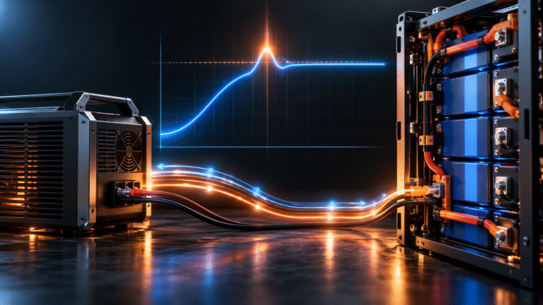
A 51.2V LiFePO4 charger is configured for a maximum charging voltage of 56.8V. During normal charging, the display stays close to the target. Then, at the moment charging current suddenly falls, a high-speed logger records a brief voltage peak above 56.8V.
The BMS may even report a cell-overvoltage event, although the charger display never appears to exceed its setting.
The customer asks a reasonable question: if the charger is programmed for 56.8V, how can the voltage ever become higher?
The answer involves transient response. Real power converters cannot adjust current and voltage infinitely fast. When load conditions change abruptly, the converter’s control loop, output capacitors, cable inductance and battery impedance can produce a short voltage excursion before the system settles back to its target.
A small, well-controlled transient is not the same as a charger continuously regulating at the wrong voltage. However, repeated or excessive overshoot can create BMS protection events and should be investigated.
Static Voltage and Transient Voltage Are Different
When technicians check a charger with a normal multimeter, they usually see a relatively stable value. This is the steady-state or slowly changing voltage.
A transient event can last for milliseconds or another very short interval. A standard display may average over that event and never show the true peak.
Therefore, the inverter might display 56.8V while a faster measurement system records a brief excursion above it.
Both readings can be technically correct because they represent different time scales.
What Causes a Voltage Overshoot?
Imagine a charger delivering 100A to the battery. The charger and its control loop are operating at a particular duty cycle to maintain that current and voltage.
Now the battery BMS suddenly reduces the permitted current or opens its charging path. The charger’s output current can drop much faster than the converter’s stored magnetic and electrical energy disappears.
For a short period, energy that was flowing toward the battery has nowhere to go at the same rate. The output voltage can rise before the charger controller reduces its command.
This is one common source of transient overshoot.
BMS Disconnection Can Make the Event More Severe
A closed-loop system ideally reduces charging current smoothly before reaching protection. For example, the BMS can communicate a lower CCL as one cell approaches its upper voltage region.
If communication is unavailable or ignored, the charger may continue at high current until the BMS makes a hard disconnection.
The electrical transition from 100A to nearly zero can be extremely abrupt.
The charger must then respond to a sudden load removal, which is more challenging than gradually tapering from 100A to 80A, then 40A and finally 10A.
This is one reason good battery-inverter communication can reduce harsh protection events.
Output Capacitors Store Energy
Power converters usually contain capacitors on their DC output or internal DC bus. These components help smooth voltage and support transient operation.
However, capacitors also store energy.
When battery current suddenly decreases, the energy stored in the converter and its output network can briefly contribute to a voltage rise.
A well-designed charger controls this behavior within its intended specification, but the amount of overshoot depends on the converter design and the connected system.
Cable Inductance Also Matters
Long battery cables are not purely resistive. They also have inductance.
Inductance resists rapid changes in current. When a large charging current suddenly changes, the cable and bus system can participate in a transient voltage event.
This becomes more relevant with long DC runs and high current.
For this reason, high-power battery systems generally benefit from appropriately short DC connections between battery and power-conversion equipment.
Why Low-Voltage High-Current Systems Can Be Sensitive
Consider a 51.2V battery charging at 200A. The power level is substantial, but the DC voltage is relatively low.
A sudden interruption of 200A represents a very large current change. The associated busbar, cables, contactors and converter must all handle that transition.
In a high-voltage system delivering the same power, current may be much lower. This changes the electrical transient environment.
Both architectures require proper design, but low-voltage high-current ESS places particular emphasis on DC current dynamics.
A Charger Display Can Miss the Peak Completely
Suppose the charger logs voltage once every second. A transient lasts 10 milliseconds.
The display may report: 56.7V → 56.8V → 56.7V
while an oscilloscope shows a brief peak above the target between those samples.
This does not mean the charger is deliberately regulating at the peak value. It means its control response allowed a short excursion.
If that peak crosses the BMS cell or pack overvoltage threshold, however, the battery may still record an alarm.
One High Cell Can Be the First to See the Problem
The pack voltage may overshoot only slightly, but one cell near the upper voltage knee can respond more strongly than the others.
Imagine 15 cells remain comfortably below their limit while one cell is already higher because of SOC or capacity imbalance. A short pack-voltage transient can push that cell across the BMS protection threshold.
The BMS then records: Cell Overvoltage
even though total pack voltage did not look dramatically abnormal on the inverter screen.
This is why cell-level data is essential when transient charging faults occur near full SOC.
Overshoot Is More Likely to Matter Near Full Charge
At moderate SOC, individual LiFePO4 cell voltage is relatively stable. Near the upper SOC region, voltage rises more steeply.
A transient that has little effect at 50% SOC may trigger protection at 98% SOC because one cell is already close to its limit.
If charging faults occur only during the last few percent, check both cell balance and charger transient behavior.
Do not assume that one of these two explanations must exclude the other. They can interact.
Example: Hard BMS Cutoff
Suppose the battery is charging at 80A. One cell reaches its protection threshold and the BMS opens the charge path.
Current drops almost instantly. The charger momentarily overshoots before reducing output.
After the cell relaxes, the BMS reconnects and charging resumes. Soon the same cell reaches the threshold again.
The user sees repeated: charge → alarm → stop → reconnect
This is not a good normal charging strategy.
The first improvement should be to prevent repeated hard cutoff through appropriate voltage settings, current tapering and BMS communication.
Example: Large Load Suddenly Disappears
Voltage transients can also occur when a system is simultaneously supplying loads and charging the battery.
Suppose solar power is high and the inverter is directing substantial energy toward both the building and battery. A large load suddenly switches off.
The EMS must redirect the excess energy quickly. If the battery is already close to its charging limit, the system may temporarily have less ability to absorb the sudden surplus.
A well-designed inverter reduces PV or grid input accordingly, but the transition is not mathematically instantaneous.
This is one reason ESS control needs adequate dynamic response.
Solar Irradiance Changes Are Usually Slower Than Electrical Switching
Cloud movement changes PV power, but many electrical events occur much faster. A contactor opening or a power stage switching can change current in milliseconds.
Therefore, a charging voltage spike that occurs at exactly the moment a BMS contactor opens is more likely to be an electrical transient than a change in sunlight.
Event timing is extremely useful in diagnosis.
Compare the timestamp of the BMS alarm with inverter logs and contactor status.
Poor Charger Control Can Create Excessive Overshoot
Every charger has some transient response, but high-quality equipment should control it within the requirements of the application.
An aging, damaged or poorly designed charger can have weak voltage regulation when the load changes rapidly.
Possible causes can include control-loop issues, degraded capacitors, incorrect firmware or equipment that was never designed for an intelligent lithium battery with rapid BMS switching.
This is especially relevant when reusing older UPS or telecom chargers originally designed around large lead-acid banks.
Lead-Acid Banks Can Behave Differently During Transients
A large lead-acid battery bank has different electrical impedance and no internal BMS contactor that suddenly opens at a cell-voltage threshold.
When the same charger is connected to a LiFePO4 battery with an intelligent BMS, the system dynamics change.
A charger that appeared stable with VRLA batteries may therefore need additional compatibility review in a lithium retrofit.
The solution is not to remove the lithium BMS. The charger and battery need to be integrated correctly.
Long Cable Runs Can Worsen Dynamic Behavior
A charger located far from the battery may use several meters of DC cable. The resistance creates steady-state voltage drop, while cable inductance affects fast current changes.
Remote voltage sensing can help correct normal steady-state cable drop, but it does not automatically solve all transient behavior.
In fact, poorly designed remote-sense wiring can create additional regulation problems if the charger control loop is not intended for that installation.
Follow the charger manufacturer’s maximum cable-length and remote-sense recommendations.
Remote Sense Wires Need Correct Routing
If the charger supports dedicated battery-voltage sensing, the sense wires should normally be connected and routed according to the manufacturer’s instructions.
Because very little current flows through them, they can measure battery-terminal voltage without the same drop as the main charging cables.
However, long unshielded or poorly routed sense wires can pick up electrical noise in some installations.
They should not be improvised without reference to the charger design.
Charging Voltage Margin Helps Reduce Hard Protection Events
The BMS high-voltage threshold should not be treated as the normal charger target.
If normal charging is configured too close to the protection threshold, even a small dynamic overshoot or cell difference can cause repeated BMS trips.
A correctly designed charging strategy leaves appropriate control margin between normal operating targets and emergency protection.
The exact margin should come from the battery manufacturer and system integration requirements rather than one universal internet number.
Lowering Current Near Full SOC Can Improve Stability
If one cell becomes voltage-sensitive near the top of charge, reducing charging current can decrease both its voltage rise and the severity of any current interruption.
This does not mean the battery must always charge slowly. High current may be perfectly acceptable during the middle SOC range, followed by a controlled reduction near the upper limit.
Closed-loop CCL control is particularly useful for this purpose.
It allows the BMS to request a smoother finish instead of waiting for an emergency overvoltage cutoff.
How to Determine Whether Overshoot Is Real
Do not rely solely on the inverter display. First compare BMS event logs and maximum cell-voltage history. If repeated overvoltage alarms occur at charging transitions, a faster measurement may be justified.
Professional diagnosis may use an oscilloscope or high-speed logger with appropriate voltage probes and current measurement.
High-power battery systems can contain dangerous energy levels, so such measurements should be performed by trained personnel.
A standard handheld meter is not designed to capture every millisecond-scale event.
Do Not Confuse Sensor Noise with a Real Voltage Spike
High-frequency power electronics generate electromagnetic noise. A poorly connected measurement instrument can display apparent spikes that are not representative of actual battery-terminal voltage.
Measurement technique matters. Probe placement, grounding, bandwidth and instrument setup can all influence the result.
Before concluding that a charger is producing dangerous overshoot, confirm the measurement method.
This is especially important when troubleshooting switching power converters.
Event Logs Can Be More Useful Than Random Measurements
Suppose the BMS records cell overvoltage at exactly 14:32:18 every time charging stops. The inverter log shows the battery contactor opening at the same second.
This correlation provides useful evidence even before an oscilloscope is connected.
If alarms occur randomly while no charging transition happens, investigate other causes such as cell imbalance, sensor errors or wiring.
Good logging can greatly reduce troubleshooting time.
Charger Firmware Can Affect Dynamic Response
Modern inverters and chargers are software-controlled. Firmware determines how quickly the converter reacts to BMS messages, how it handles current reduction and how it responds when the battery disconnects.
Incompatibility or firmware defects can therefore influence charging transients.
Firmware should only be updated according to manufacturer guidance and verified compatibility. Randomly installing a newer version is not a safe universal solution.
Parallel Batteries Add Another Dynamic Layer
In a multi-battery parallel system, one module may disconnect while others remain connected.
The total battery-bank impedance and current-sharing condition change suddenly. The PCS must adjust output accordingly.
If four modules are charging and one goes offline, the remaining three can experience a rapid increase in current unless the master BMS or inverter reduces total power.
This is one reason modular battery systems need coordinated communication and correctly designed busbars.
High-Voltage ESS Uses the Same Principle at Larger Scale
Commercial high-voltage battery racks may contain multiple series modules, contactors and a master BMS. The PCS can be transferring tens or hundreds of kilowatts.
Dynamic coordination during contactor operation and current limitation becomes even more important.
Precharge, communication, DC-link control and fault response should all be covered in the battery-PCS interface design.
Large ESS integration is not simply a matter of matching nominal voltage.
A Practical Troubleshooting Sequence
When a battery experiences high-voltage alarms near the end of charging, first review the configured charge voltage and BMS cell-voltage data. Then check whether charging current is being reduced smoothly before the alarm. Review BMS CCL, contactor status and inverter logs around the same timestamp.
If the event occurs exactly when current changes abruptly, investigate charger transient behavior, DC cable length and communication response. If one cell is consistently much higher even during steady charging, cell balance may be the primary issue.
Both steady-state and transient data should be considered.
Do Not Raise BMS Protection Thresholds to Hide the Problem
If a charger transient repeatedly causes BMS overvoltage, increasing the BMS protection threshold is not the appropriate first solution.
The protection exists to prevent the cells from reaching unacceptable conditions.
Correct the normal operating behavior instead. This may involve charge-voltage settings, current taper, communication integration, charger firmware, cable design or charger replacement.
The BMS should remain the final safety layer.
What B2B Buyers Should Ask a Charger Supplier
For high-value ESS projects, charger evaluation should include more than rated voltage and current. Useful information includes output-voltage regulation, behavior during sudden load changes, compatibility with battery contactor switching, CAN/RS485 control capability and any relevant transient-response specification.
For industrial integration, the battery and charger manufacturers should exchange interface information before shipment.
This is particularly important when one supplier provides the battery and another supplies the PCS or rectifier.
Conclusion
A LiFePO4 charger configured for 56.8V can still experience a brief transient voltage excursion above that value when charging current changes rapidly. This does not necessarily mean the charger is continuously regulating at the wrong voltage, but excessive overshoot can trigger cell or pack overvoltage protection.
The most important factors include control-loop response, abrupt BMS disconnection, stored energy in the converter, DC cable dynamics, cell balance and charging current near full SOC.
A stable ESS should avoid repeatedly reaching hard BMS protection. Normal charger control and BMS communication should reduce current before the protection threshold is reached.
HIZN supplies LiFePO4 energy storage batteries with intelligent BMS and CAN/RS485 communication for residential, telecom and commercial systems.
If your battery records high-voltage protection even though the inverter charging setting appears correct, send us the battery model, inverter/charger model, charge-voltage setting, maximum cell-voltage history and BMS alarm log. We can help determine whether the issue is related to cell imbalance, charging settings or transient system behavior.