
Introduction
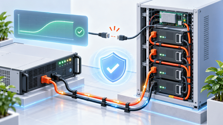
A customer has a 51.2V LiFePO4 battery and a 48V hybrid inverter. Electrically, the voltage range appears compatible, but the inverter does not support the battery’s CAN protocol. The customer therefore asks a practical question: can the battery still be used safely, or must the inverter be replaced?
In many systems, a LiFePO4 battery can operate without closed-loop CAN or RS485 communication if the battery manufacturer permits open-loop or voltage-mode operation and the inverter allows appropriate manual settings. The battery BMS still monitors individual cells, current and temperature internally, while the inverter controls charging using fixed voltage and current limits.
However, voltage-mode operation requires more careful commissioning because the inverter no longer receives dynamic battery information such as Charge Current Limit, Charge Voltage Limit, temperature restrictions or accurate SOC directly from the BMS. The installation therefore needs enough operating margin to avoid relying on emergency BMS protection during normal daily charging.
Closed-Loop and Open-Loop Charging Are Different
In a closed-loop system, the battery and inverter communicate continuously. The BMS can tell the inverter how much charging current is currently permitted, whether temperature requires derating and whether the battery is approaching its upper charging limit. The inverter can then adapt its output dynamically.
In open-loop operation, the inverter does not receive these instructions. It follows manually configured parameters such as charging voltage, maximum charge current, low-voltage cutoff and recharge voltage. The BMS remains active, but it acts mainly as the final protective layer rather than the normal charging controller.
Both approaches can work, but they provide different levels of coordination.
No CAN Does Not Mean No BMS
One common misunderstanding is that a battery without inverter communication has no protection. This is incorrect. The internal BMS can still monitor cell voltage, pack current and temperature and can still disconnect charging or discharging if necessary.
What disappears is the information exchange between the BMS and inverter. The inverter may no longer know that the battery is hot, that one cell is approaching high voltage or that the BMS wants charging current reduced from 100A to 30A.Therefore, manual inverter settings become more important.
First Confirm That the Battery Manufacturer Allows Voltage-Mode Operation
Not every energy storage battery is intended to operate without communication. Some integrated ESS products require a specific inverter protocol for normal startup or contactor control.
Before configuring User Defined, Lead Acid or Custom mode, confirm that the battery supplier explicitly allows open-loop operation.
If the battery requires a communication handshake before enabling its main contactor, manually entering a voltage setting will not solve the compatibility problem.
Use the Exact Battery Charging Specification
When CAN is unavailable, the inverter cannot automatically receive the manufacturer’s preferred charging limits. The installer must enter them manually.
Typical parameters that need to be confirmed include charging-voltage target, maximum or recommended charging current, low-voltage cutoff, discharge recovery or restart voltage, float behavior and equalization setting.
These values should come from the exact battery model. Two products can both be labeled “51.2V 100Ah LiFePO4” while using different BMS thresholds and recommended charging strategies.
Avoid copying settings from another brand simply because nominal voltage is the same.
Charging Voltage Should Stay Below BMS Protection
The inverter’s normal charging target should not be set equal to the battery’s emergency high-voltage protection threshold. If the charger routinely pushes the battery all the way to BMS cutoff, the system may repeatedly stop and reconnect near full SOC.
A properly configured open-loop system should finish normal charging before BMS emergency protection is required.
This operating margin becomes especially important when there is no CAN communication, because the BMS cannot ask the inverter to taper current dynamically as one cell approaches its upper limit.
Charge Current Needs Conservative Margin
Suppose a battery has a 200A BMS. That does not automatically mean the inverter should be configured for 200A charging.
The battery supplier may recommend a substantially lower routine charging current. Temperature, cell design, terminal rating and intended application all influence the appropriate value.
Without closed-loop communication, a moderate fixed charging current can provide more margin under changing conditions than operating continuously near the battery’s maximum electronic limit.
The correct target should still meet the required recharge time without forcing the system to depend on BMS overcurrent or temperature protection.
Temperature Protection Is a Major Difference
Closed-loop systems can reduce charge current before temperature reaches a hard cutoff. In voltage mode, the inverter may continue requesting the same charging current because it has no battery-temperature information.
If the battery becomes too hot or too cold, the BMS may eventually block charging completely.
This means open-loop installations require particular attention to the environmental operating range. A fixed current that works well in an air-conditioned room may not be ideal in an outdoor cabinet in summer or at a cold mountain site.
Low-Temperature Charging Deserves Extra Caution
LiFePO4 batteries often have stricter temperature requirements for charging than discharging. A battery may still power loads when cold while refusing charging.
With CAN communication, the inverter may receive a zero or reduced Charge Current Limit. Without CAN, the inverter can continue applying charging voltage until the BMS blocks the charging path.
This can still protect the cells, but normal system behavior becomes less smooth. For cold-climate projects, a battery with integrated heating or a compatible temperature-management strategy can be particularly valuable.
Equalization Should Normally Be Disabled
Many inverters expose manual settings through a Lead Acid or User Defined battery menu. If the installer enters custom lithium voltages but leaves automatic equalization enabled, the inverter may periodically raise voltage according to its original lead-acid logic.
The system might operate normally for several weeks and then suddenly trigger BMS high-voltage protection during an automatic equalization event.
For LiFePO4 voltage-mode operation, review every lead-acid-related function, not just the main charging voltage.
Float Behavior Also Needs Review
Some inverters require a float-voltage value even when the battery does not need traditional lead-acid float charging. Depending on the inverter, this value may be used as a lower standby voltage after charging completes.
The battery manufacturer may recommend disabling float, using a lower compatible standby value or configuring the inverter in a way that avoids holding the battery continuously near maximum SOC.
The correct setting depends on how the inverter implements its charging stages. The word “float” alone does not describe the actual behavior.
SOC Display Becomes Less Reliable Without Communication
One of the biggest practical differences is SOC reporting. If the inverter cannot read SOC from the BMS, it may estimate battery SOC mainly from voltage.
This is difficult with LiFePO4 because the voltage curve is relatively flat through much of the usable SOC range. A displayed 70% or 50% calculated only from voltage may therefore be inaccurate.
The battery’s own LCD or BMS application may provide a better SOC estimate, but even BMS SOC can require periodic synchronization.
For system control, do not assume the inverter’s voltage-based SOC is equivalent to the battery’s BMS SOC.
Time-of-Use Control Can Become Less Precise
Suppose an inverter is programmed to stop discharge at 25% SOC and recharge to 80%. If it has no actual BMS SOC data, those percentages may be estimates derived from voltage.
The resulting operating window can differ from what the user expects.
Where precise SOC-based dispatch is important, closed-loop communication or an external battery monitor may be preferable.For simple backup systems, voltage-based control may still be acceptable if thresholds are carefully selected.
Low-Voltage Cutoff Requires Careful Coordination
The inverter should normally stop discharging before the battery reaches hard BMS undervoltage protection. If the inverter routinely continues until the BMS shuts down, restarting the complete system can become more difficult.
In open-loop operation, the inverter must therefore use a conservative low-voltage cutoff and a suitable recovery threshold.
The objective is for the inverter to end normal discharge while the battery still has enough voltage and BMS power to remain online.
Hard BMS shutdown should be an emergency condition, not the daily discharge target.
Why Voltage-Based SOC Is Especially Weak Under Load
Battery voltage changes according to current. A 51.2V battery supplying a heavy load may show a lower terminal voltage than the same battery at rest.
If the inverter interprets that temporary voltage sag as very low SOC, it can disconnect loads earlier than necessary.When the load disappears, battery voltage rises again and the inverter may reconnect.
This creates a possible cycle of disconnect and reconnect if thresholds are poorly chosen.Open-loop voltage settings should therefore consider real load current, not only resting voltage.
Parallel Batteries Need Additional Coordination
Suppose four 51.2V modules are connected in parallel without CAN communication to the inverter. The inverter sees only the common battery-bus voltage.
It does not know whether all four modules are online. If one module disconnects because of an internal alarm, the inverter may continue using the same total charging-current setting.The remaining three batteries then carry more current each.
A conservative current design and module-level monitoring become more important when the inverter lacks direct knowledge of the active battery count.
Battery-to-Battery Communication May Still Exist
Even if the inverter does not communicate with the battery bank, parallel battery modules may still communicate with one another.
A master BMS can coordinate module status, SOC or internal current limits while the inverter itself operates in voltage mode.
This is different from having no battery communication anywhere.Before commissioning, understand both communication layers: battery-to-battery and battery-to-inverter.
Example: 51.2V 200Ah Battery with an Unsupported Inverter
Consider a 51.2V 200Ah battery whose manufacturer permits open-loop operation. The inverter supports a user-defined 48V lithium profile but no compatible CAN protocol.
The installer enters the battery supplier’s approved charging-voltage range, chooses a routine charge current within specification, disables equalization and sets conservative discharge and recharge thresholds.
The system can then charge and discharge based on voltage while the BMS remains active internally.
What the inverter loses is dynamic information. It cannot automatically reduce current because of cell temperature, cannot display true BMS SOC and may not know about module-level alarms.
That trade-off should be understood before deployment.
When Closed-Loop Communication Is Strongly Preferred
Voltage mode can be practical for simple systems, but closed-loop communication becomes more valuable as system complexity increases.
Large parallel battery banks, high-power commercial ESS, systems operating close to thermal/current limits and installations requiring precise SOC dispatch all benefit from coordinated BMS control.
For these applications, choosing a supported inverter protocol at the beginning is usually better than relying indefinitely on fixed voltage settings.
Do Not Select “Lithium” Mode Blindly
An inverter may include a menu item labeled “Lithium Battery.” That label does not guarantee that every lithium battery protocol is supported.
Some lithium modes require a particular CAN protocol. If the expected battery is not detected, the inverter may alarm or disable charging entirely.
Other inverters allow Lithium mode without communication and simply use fixed settings.
Read the inverter manual and confirm exactly what the selected mode does.
A Practical Commissioning Test
After configuring voltage mode, start with moderate charging and discharging power. Monitor pack voltage, individual cell voltages, battery current, temperature and BMS alarms.
Confirm that normal charging stops without high-voltage protection and that normal discharge stops before hard BMS undervoltage shutdown.
Then test the expected operating load and charging power gradually.
A system that appears stable for ten minutes should still be observed near high SOC and low SOC because those are the conditions where fixed voltage settings are most likely to expose problems.
Information Distributors Should Provide
For batteries that support open-loop operation, distributors should provide more than a nominal voltage. A useful compatibility sheet should state recommended charge voltage, charge-current range, low-voltage recommendations, whether float should be used, whether equalization must be disabled and whether communication is optional or mandatory.
This reduces installer guesswork and after-sales disputes.
The customer should also provide the inverter brand and model before purchasing whenever possible.
Conclusion
A 51.2V LiFePO4 battery can often operate safely without CAN or RS485 communication if the battery manufacturer permits voltage-mode operation and the inverter can be configured correctly.
The system must then rely more heavily on fixed charging voltage, fixed current limits, conservative low-voltage settings and internal BMS protection. SOC reporting and dynamic current control will usually be less sophisticated than in a closed-loop system.
For simple backup or off-grid applications, this can be a practical solution. For large commercial or high-power systems, compatible closed-loop communication is generally preferable.
HIZN supplies 48V/51.2V LiFePO4 energy storage batteries with CAN/RS485 communication and can also provide model-specific charging parameters for compatible open-loop applications.
If your inverter does not support the battery’s CAN protocol, send us the inverter model, battery model, planned charging current and application. We can help determine whether voltage-mode operation is suitable and which battery-side parameters need to be confirmed before commissioning.