
Introduction
A commercial ESS uses a 100kW bidirectional PCS. The LiFePO4 battery can accept 100kW, the grid connection is adequate and battery SOC is low. However, actual battery charging stops around 80kW while the PCS simultaneously provides reactive-power support to the site.
The customer sees the PCS nameplate and asks: if it is a 100kW machine, why isn’t the battery receiving the full 100kW?
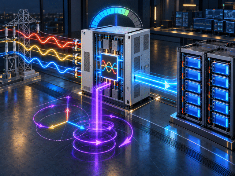
The answer is that many grid-connected power converters are limited not only by real power in kilowatts but also by apparent power in kilovolt-amperes. When the PCS is asked to exchange reactive power with the grid, part of its current capacity is already being used.
The remaining current available for real battery charging can therefore decrease.
For commercial and industrial ESS projects, understanding the relationship between kW, kVAR and kVA is essential when evaluating actual charging power.
Real Power Is the Energy That Charges the Battery
Real power is measured in:kW
This is the component of AC power that can perform useful work or be converted into stored battery energy.
If the PCS imports 80kW of real power from the grid, that power can be converted through the PCS and delivered toward the battery, minus conversion losses.
When calculating battery recovery time, kW is therefore the most directly relevant AC power quantity.
Reactive Power Is Different
Reactive power is measured in: kVAR
It moves energy back and forth between the electrical source and reactive components such as motors, transformers and capacitive or inductive loads.
Reactive power does not directly become stored battery energy.However, it still requires current to flow through the PCS semiconductors, cables and switchgear.That current uses part of the equipment’s electrical capacity.
Apparent Power Combines Both
Apparent power is measured in: kVA
For a simplified sinusoidal system: kVA² = kW² + kVAR²
This relationship explains why a PCS cannot always deliver maximum real charging power while simultaneously providing significant reactive power.
If the inverter’s apparent-power capability is already partly occupied by kVAR, less kVA remains available for kW.
Example: 100kVA PCS
Suppose a PCS has an apparent-power limit of: 100kVA
and the site requests: 60kVAR of reactive support.
The maximum remaining theoretical real-power capability is approximately:
√(100² − 60²) = 80kW
Therefore, even though the equipment may commonly be referred to as a 100kW PCS, it cannot simultaneously provide 100kW of real battery charging and 60kVAR of reactive power if its total apparent-power limit is 100kVA.
The converter has reached its current capacity.
The Battery Can Be Completely Normal
In this situation, the battery may be at 30% SOC, temperature may be perfect and BMS Charge Current Limit may permit the full requested power.
The PCS is still unable to charge faster because the limitation exists on the AC conversion side. This is similar to a three-phase phase-current limit: the battery is not the bottleneck.
When troubleshooting commercial ESS charging, always compare the PCS’s real-power command with its reactive-power command and apparent-power rating.
Why Would an ESS Provide Reactive Power?
Commercial and utility-connected power converters may be required or configured to support voltage and power factor. The PCS may operate at a specified power factor or directly follow a reactive-power command.
Possible objectives include improving facility power factor, meeting grid-code requirements, supporting local voltage or participating in utility services.
If these functions are enabled, the ESS is doing more than simply charging and discharging the battery. Its current capacity is being shared between active and reactive power.
Power Factor Connects kW and kVA
Power factor can be expressed approximately as: PF = kW ÷ kVA
At unity power factor, PF is approximately 1.0 and nearly all apparent power is real power. At lower power factor, more current is required for the same kW.
For example, delivering 80kW at PF 0.8 requires approximately: 100kVA of apparent power. This is why power-factor requirements can affect maximum battery charging power.
Nameplate Terminology Can Be Confusing
Some manufacturers describe their PCS primarily by kW, others also specify kVA, maximum AC current and allowable reactive-power range.
A buyer should not assume that “100kW PCS” means “100kW real power available under every reactive-power condition.”
The technical datasheet should show whether the unit can provide reactive power in addition to rated real power or whether the two functions share the same current limit.
Some equipment may have short-term or oversized apparent-power capability. Others may not. The exact performance must come from the PCS manufacturer.
Example: Power Factor Set to 0.9
Suppose the site requires the PCS to operate at a power factor of 0.9 and the apparent-power capability is 100kVA.
Maximum real power is approximately: 100kVA × 0.9 = 90kW
This means the charger may be limited to around 90kW of AC real power before considering conversion losses and battery-side limits.
The battery may therefore receive somewhat less than 90kW. A project calculation based on a full 100kW battery charge rate would underestimate recharge time.
Battery-Side Power Is Lower Than AC Real Power
Even when the PCS imports 90kW of real AC power, not all of it reaches the battery because conversion efficiency is below 100%. Suppose PCS efficiency is 96%.
Approximate battery-side power could be around: 90kW × 0.96 = 86.4kW before considering auxiliary consumption.
This distinction becomes important when specifying how quickly a 500kWh or 1MWh battery must recover.
Charging-Time Example
Suppose a 500kWh battery must restore: 300kWh of energy.
If the project assumes 100kW battery charging, idealized recovery is: 300 ÷ 100 = 3 hours
Now imagine reactive-power operation reduces usable battery charging power to around 85kW.
Recovery becomes: 300 ÷ 85 ≈ 3.5 hours
The difference may be operationally significant if the battery has a narrow charging window.
Reactive Power Can Change Throughout the Day
The limitation may not be constant. During periods when the facility’s motors or transformers create a poor power factor, the PCS may provide more kVAR and therefore have less capacity for battery charging.
Later, when reactive demand decreases, the same PCS can charge the battery faster. The customer sees charging power moving between 70kW, 85kW and 100kW without any BMS setting changing. A time-correlated record of kW, kVAR and kVA can explain this behavior.
The PCS Current Rating Is the Physical Foundation
At the hardware level, power semiconductor devices and AC conductors have current limits. Whether that current produces real power or reactive power, it still flows through the equipment.
This is why the converter cannot ignore reactive power simply because the battery only stores real energy. Once RMS current approaches the PCS limit, the controller must reduce one component of power or another.
Three-Phase Current Still Matters
For a three-phase PCS, apparent power is related to line voltage and current. At a given AC voltage, increasing kVAR increases the required RMS current.
If one phase or all phases approach the maximum current limit, the PCS can no longer increase battery-charging kW. This connects reactive-power limitation with the phase-loading issues found in commercial ESS projects. The electrical constraints exist simultaneously rather than independently.
Grid Voltage Also Changes the Available Current Margin
For the same kVA, lower AC voltage requires higher current. If grid voltage drops during a period of heavy local demand, the PCS may approach its current limit sooner.
The combination of low voltage and reactive-power support can therefore reduce maximum real charging power more than expected. This effect is especially relevant in weak industrial grids.
Reactive Power May Be Requested Even at Zero Battery Power
Some bidirectional PCS equipment can provide reactive-power support even when the battery is neither charging nor discharging significantly.
In that state, battery kW can be close to zero while AC current still flows because the PCS is providing kVAR. This can confuse users who assume that no battery power means the inverter should also show almost no AC current. Reactive-power operation explains why that assumption is not always valid.
Does Reactive Power Consume Battery Energy?
Ideal reactive power does not represent net energy transfer in the same way as real power. However, the PCS still has internal losses while generating reactive current.
Those losses require a small amount of real energy. Depending on system state, that energy may come from the grid or battery.
Therefore, reactive-power support is not completely lossless even though the requested kVAR itself is not stored in or removed from the battery as useful energy.
EMS Priority Determines Which Service Wins
A commercial EMS may need to decide between several objectives: recharge the battery, support site power factor, limit transformer demand, maintain backup reserve and follow utility commands.
If the PCS does not have enough capacity to perform all of them simultaneously at full power, the control system needs a priority strategy.
For example, a site may prioritize grid-code reactive-power requirements over maximum battery charging.
Another project may prioritize battery recovery after an outage and temporarily reduce non-essential reactive-power support. This decision belongs to the system-control design.
Peak Shaving Can Compete with Reactive Support
Suppose the battery is charging at 80kW when facility demand is low. A large motor starts and the site’s power factor deteriorates.
The PCS may reduce charging power and provide more reactive support. Later, the building approaches its grid-demand limit, and the PCS may even reverse direction to discharge real power while still providing reactive current.
The battery system is now simultaneously participating in energy management and power-quality control. A simple “charger kW” view is no longer enough to explain its operation.
Solar Storage Can Have the Same Constraint
A commercial solar plant has excess midday PV and wants to store 100kW in the battery. At the same time, the PCS is commanded to support voltage using reactive power.
If apparent-power capacity is limited, some solar energy may need to be curtailed because the battery PCS cannot absorb the full 100kW while maintaining the reactive-power requirement.
Increasing battery capacity alone will not solve the problem. The bottleneck is PCS kVA.
Oversizing PCS Apparent Power Can Create More Flexibility
For projects requiring simultaneous full battery power and significant reactive support, the PCS may need an apparent-power rating higher than the maximum real battery power.
For example, a 100kW battery-power requirement plus substantial reactive capability might justify selecting equipment with greater kVA headroom.
Whether this is necessary depends on the grid code, site power factor and expected simultaneous operating conditions. This should be evaluated during system design rather than after commissioning.
Transformer and Switchgear Must Also Carry the Current
Reactive current does not only pass through the PCS. It also affects cables, breakers and transformers on the AC side. Therefore, apparent-power calculations matter for upstream equipment too.
A transformer sized only around battery kW without considering reactive-power requirements can become overloaded even if real power remains within expectations.
Commercial ESS design should coordinate kW, kVAR, kVA and current through the complete electrical path.
Battery BMS Still Sets an Independent Limit
PCS apparent-power capability is only one limitation. The BMS can simultaneously impose a lower battery-side charge limit because of SOC, cell voltage or temperature.
Suppose the PCS could currently provide 80kW after reactive-power allocation, but the BMS permits only 60kW. Actual battery charging is limited to 60kW.
Later, the BMS allows 100kW but PCS reactive operation still limits real power to 80kW. Now the PCS becomes the bottleneck. The lowest active limit always wins.
How to Diagnose Unexpectedly Low Charging Power
When a commercial battery is not reaching the expected charging kW, record PCS real power, reactive power, apparent power, power factor, AC voltage, AC current, battery voltage, BMS CCL and actual battery power.
If kVA or AC current is already near the PCS rating while kW is below its nominal value, reactive-power demand may explain the difference.
If both kW and kVA are low, look elsewhere for the limitation. This approach is much more useful than assuming the battery is refusing charge.
Information Needed for a Commercial ESS RFQ
A serious commercial ESS specification should include more than battery kWh and PCS kW. Buyers should also state grid voltage, required power factor, reactive-power capability, whether simultaneous P/Q operation is required and any local utility-grid requirements.
For example, “100kW/200kWh ESS” is incomplete if the PCS must also provide ±60kVAR continuously. These requirements influence PCS sizing and actual battery charging performance.
Conclusion
A PCS rated for 100kW may not always provide 100kW of battery charging while simultaneously supporting reactive power.
Real power, reactive power and apparent power are linked by the converter’s current and kVA limits. When kVAR increases, the available kW may decrease unless the PCS has sufficient apparent-power headroom.
For commercial ESS projects, charging calculations should therefore consider kW, kVAR, kVA, power factor, AC voltage and conversion efficiency, not battery capacity alone.
HIZN supplies LiFePO4 battery systems for commercial and industrial energy storage and can provide battery-side voltage, current and BMS interface information for PCS integration.
If your project requires simultaneous battery charging and reactive-power support, send us the battery capacity, PCS model, grid voltage, required kW/kVAR and BMS charge-current limits. We can help confirm the battery-side requirements that should be coordinated with the PCS supplier.